Looking back, there are a couple of gaps. October was swallowed up by installation work at York Maze, and June saw the arrival and installation of our coil winding facility, so I found little time for blogging.
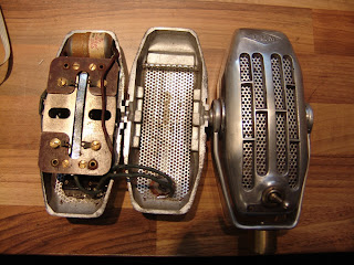
December’s Microphones of the Month are these impressive art deco-style LEM ribbon mics. LEM are a French manufacturer who still make reporter-style dynamic microphones. They used to make really cool looking ribbons!
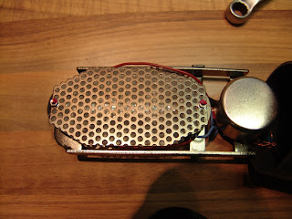
LEM 305 / 306 microphones
These are all high impedance mics, and although they are substantially similar, there are some subtle differences between the models.
Inside the LEMs
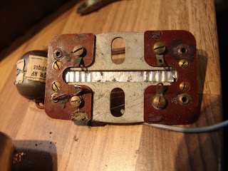
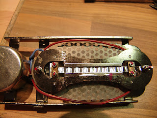
The microphones all use large, 6 mm wide ribbon which sit between two steel pole-pieces. One of the mics arrived with fully corrugated ribbons, whereas the others had thicker, half-corrgated ribbons.
LEM 306 ribbon motor with holes in the pole-pieces.
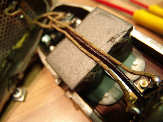
The magnets are different – in the one, a pair of block magnets are connected at the rear by a welded steel plate, whereas two have a pair of horsehoe magnets. The smaller, more powerful magnets in the later models allow holes to be made in the pole-pieces, which (in theory at least) should give better high frequency response.
LEM 305 magnets
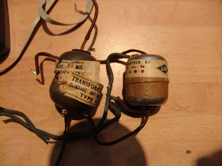
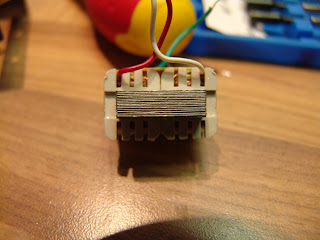
The other obvious difference between the microphones is the transformer, with the older models having a larger, iron core, whereas the newer ones have smaller mu-metal laminations, and these transformers are housed in screening cans.
Sadly all three transformers were faulty – the old rubber insulation around them had become brittle with time and the wires were broken. We were able to re-wind the two, but the third had suffered from an earlier bodged repair attempt, and had to be replaced completely. In this case we took the opportunity to give it a 300 ohm output impedance.
LEM transformers in metal screening cans
LEM transformer with larger core
Once serviced, these mics work well, with fair output for old ribbon mics, and a good vintage tone.
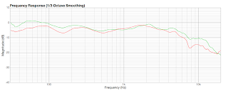
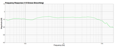
Frequency plots for LEM ribbon microphones, after servicing.
Update 5/1/15: Thanks to Philippe Le Gourdiol for sending in this picture of his LEM ribbon microphone, which is a low impedance model with a high-pass filter. The filter inductor is located below the motor assembly…
Here is a little curiosity. STC are mostly known for making high quality ribbon and dynamic mics, inclduing the much loved 4033 and 4038 models. But they also made condenser mics, and this nice little STC condenser mic came in for service recently….
It is model number 4136, and according to its specification sheet would originally have had its own power supply, which ran on either mains voltage or five 9 Volt batteries. Unfortunately the mic was bought without the power supply. The power would have been supplied to one pin of the XLR connector, ground to another, and (unbalanced) audio to the third. The capsule has a sintered glass, metallised backplate.
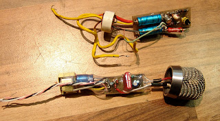
The battery supply suggests that 45V should be sufficient to power the mic. There was some corrosion on the circuit board from leaky capacitors, and without the original PSU, or knowledge of the operating voltage, it seemed sensible to create a balanced phantom powered circuit, loosely based on the Neumann KM84 – this is shown below along with the original circuit.
In practice, the conversion worked nicely, and despite its age and rough looks, the capsule gave a relatively even response, with a broadly cardioid pattern.
I found this ribbon / magnet / motor assembly inside a Reslo RBL microphone…
..which is very different from the usual Reslo motor design.
I have never seen this type, and I don’t know if it is an attempt by Reslo to upgrade or modernise the old design, a transplant from another make of microphone, or a good quality DIY repair job. It remains a mystery!
This is the inside of a client’s Avantone dual ribbon microphone, which was in pretty bad shape.
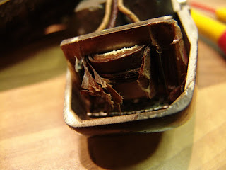
The metal plating on the neodynium magnets has suffered a catastrophic failure, and in doing so has been pushed out, crunching the ribbons and covering the whole assembly with powdered neodynium alloy. Not good.
The cause of the failure is still a mystery – perhaps it could be due to a process failure in a batch of magnets, or maybe the mic was exposed to an excessively humid environment.
I have seen other mics with signs of flaking on the magnets, but nothing this serious. Neodynes are still a relatively new magnet technology, and how they will stand up to years of studio use and abuse remains to be seen.
Happily, we were able to bring the mic back to life by replacing the magnets and of course re-ribboning the mic.
Ronnie at Diesel Studios in Italy sent in a pair of T-bone RB500 ribbon mics for service and upgrade. Ronnie asked for some photos of the process, and I thought they would make a nice photo-blog.
Here is one of the mics on arrival…
Inside the body, there is further screening to protect the ribbon, and the transformer sits in a metal can.
One of the old ribbons.
This one is not so great!
New 1.8 micrometer ribbons….
The old transformer has primary DC resistance of 90 milliohms, and 30 ohms for the secondary. Those laminations are not very well packed.
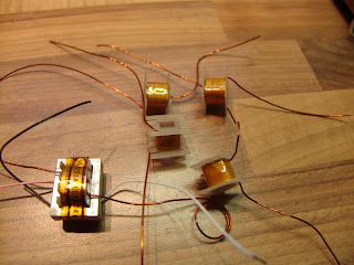
Winding new transformers for the mics.
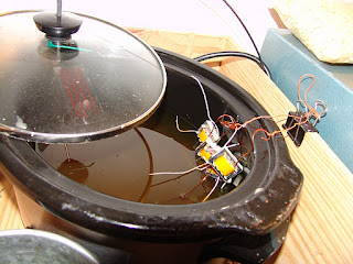
Potting the transformers in the wax bath keeps the coils and laminations from vibrating….
The finished transformers. We may as well re-use the metal can for some extra screening.
The Sony C38b is held by a yoke, and the stand mount contains a pair of rubber diaphragms which provide a little bit of shock absorption for the mic.
With time the rubber ion this one has perished, leaving the mic to flop around, rattle, and – worst of all – fall off the mic stand.
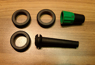
Here is how i fixed one with a strain relief rubber grommet, three rubber rings, and a jack plug bushing. The rubber rings are 23mm OD, 16 mm ID, and are the kind available (at least here in the UK) for fitting metal boxes for a ring mains, to stop the cables rubbing. The grommet measured 14 mm OD, 5 mm ID, with a recessed ridge diameter of 9 mm, and is cut off at the bottom to fit.
Firstly, unscrew the large grey knurled nut and take the mount apart. All the old rubber needs to be cut away. Then push the new strain relief grommet into the centre hole in the large grey knurled nut. Remove the bottom nut from the centre screw that is attached to the yoke, and push this into the centre of the grommet. It should look like this….
Then, pack the barrel of the mount with three rubber o-rings.
I then used a bushing from a Neutrik jack plug and inserted this into the centre.
Finally, push the re-rubbered yoke into the centre, and firmly hand-tighten the knurled nut. It should look like this.
The new assembly doesn’t give as much ‘bounce’ as the original, but it holds well, doesn’t rattle, and most importantly, it doesn’t fall off!
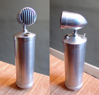
Big old German bottle microphone (flaschenmikrofon)
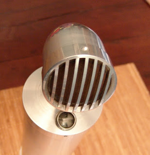
This time-capsule condition, stunning bottle mic is a recent ebay find, but we know very little about it! So, if you recognise this one, or have any further information, please get in touch.
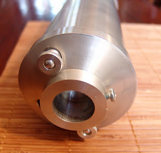
In looks, this is very much in the style of an RFT CM7049 or a Neumann CMV3, but doesn’t match any of the models that I am aware of by those manufacturers. The mic stands around 320 mm tall by 80 mm diameter, and is beautifully machined from aluminium, so we’ll call him ‘Big Al’.
The bottom bell is secured by two thumbnuts, which make access to the tube and battery compartment very easy.
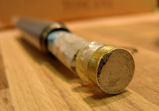
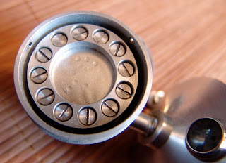
The capsule is held in place by a clamping ring with 12 screws, and the diaphragm looks to be either nickel, or some kind of metallised film. It is not possible to get the capsule out of the head without removing these screws – not something I really want to be doing. It is even possible to work out the backplate hole pattern from the dents in the diaphragm.
Bottle microphone capsule
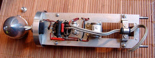
The tube is a Telefunken DAF11 which dates back to the 1940s. I haven’t met one of these before, but the datasheet is available at Frank’s, and shows it to be a diode and pentode in the same shell, with a common heater & cathode.
DAF11 tube
The diode part is not used in this mic. The heater supply is a modest 1.2V at 50 mA, and is designed to run from a battery cell.
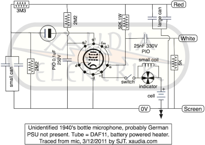
DAF11 bottle mic schematic
I traced out the circuit – the heater supply does indeed come from a battery, and there is a space inside the mic for a large cell. The switch on the top of the mic breaks the filament supply, saving battery power and (eventually) muting the mic, and there is a Neumann / RFT style indicator. in the top.
The capacitors in the rectangular metal cans are not labelled, but each can contains a pair of caps with a common negative terminal. On the bench, all four caps measure 1.0 ± 0.2 uF, and the different can sizes must reflect different voltage ratings.
There is no grid resistor present in the mic – either it has been removed for some reason, or the design relies on grid leak to set the bias.
Update 7/12/2011
We had a nice little discussion about this mic over at GroupDIY.
This Stellar RM3 ribbon microphone recently came into the Xaudia workshop for a transformer upgrade and new ribbon, which of course gives us a chance to poke around inside and take some photos.
Stellar RM3 with new Xaudia transformer and ribbon. The old transformer in in the foreground
The design closely follows the Speiden / B&O / Royer style of microphones – possibly a little too closely for comfort! Like the B&O mics, the ribbon frame slides out of the top, along with the transformer and lots of synthetic woolly packing. The body forms part of the magnetic return circuit, so it was good to see that this one was made of a magnetic steel, rather than brass or aluminium. In my opinion this is one of the better made of the budget ribbon mics.
As is commonly the case with budget microphones, the design is let down a little by the transformer, which measured 47 mΩ (milliohms) on the primary winding, and 90 Ω for the secondary, with a turns ratio of 1:54. Overall the mic gave a measured output impedance of about 650 Ω, of which over 200 ohms is pure DC resistance from the transformer. And in ribbon mics, resistance equals noise.
The new Xaudia 595/40 transformer (in this case a 1:40 ratio) has DC resistances of 0.02 Ω for the primary and 16 ohms for the secondary – much lower than the stock trannie. Although the lower transformer ratio would be expected drop the output level of -2.6 dB, the thinner, lighter ribbon gives an almost equal but opposite effect, and the output levels before and after are very similar. However, the lower DC resistance of the replacement transformer gives much lower noise, and the larger core allows higher sound pressure levels before the onset of saturation.