Very early tube ribbon microphone inspired by the RCA PB17

Ev of Vashion Island sent in these pictures of his wonderful tube ribbon microphone and has kindly agreed to share the photographs and description on this blog. The mic is a little bit of a mystery as it appears to be similar to an early Marconi design and the RCA PB17, yet has no maker’s mark and is different in many details.

The mic is clearly influenced by Harry Olsen’s design as described in his 1932 patent and the magnetic field for the ribbon is provided by an electromagnet, which is very rare and only usually found in the very earliest ribbon mics; this approach became redundant very quickly as strong permanent magnets became available.

As I have not inspected this microphone myself I will use Ev’s description and photographs – Ev’s comments are in italics:

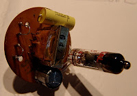
“The outside diameter of the cylinder is 4.75 inches or 210mm. The  cylinder is aluminum. the top end cap and plate are machined aluminum. The hemispherical bottom cap is also machined aluminum.

The yoke mount is steel flatbar (I believe the PB17 yoke mount is made of cast metal).

There are three transformers including the one for the electromagnet.

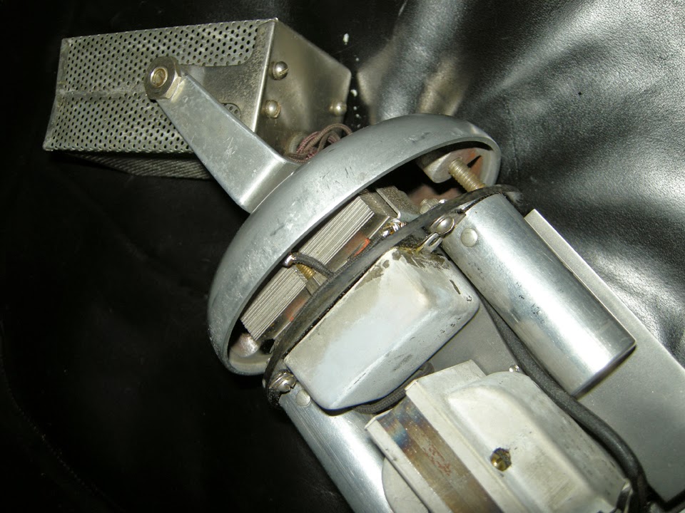
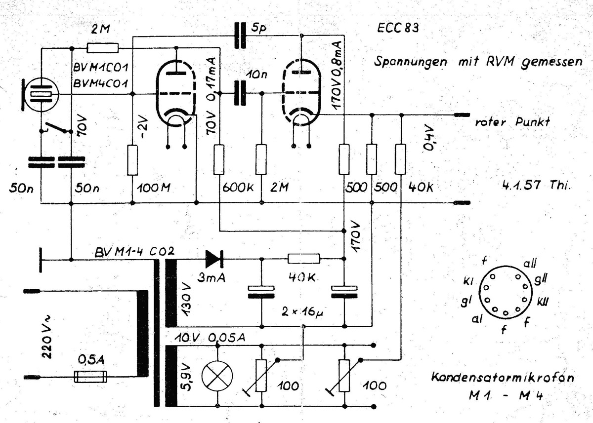
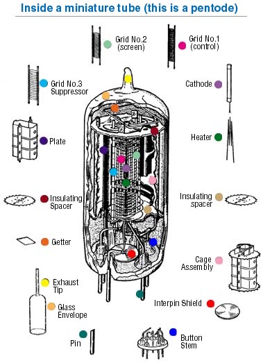
Instead of having three UX864 tubes it uses two unknown tubes, one has 5 pins with a wire attached to the top, and the other is 6 pins. 


The resistors are made by Morrill, Germany. The transformers and capacitors have no makers marks that I can see. Whoever made this microphone obviously knew what they were doing. I wonder if this was a prototype made by RCA, or perhaps it is European (because of the German resistors)?

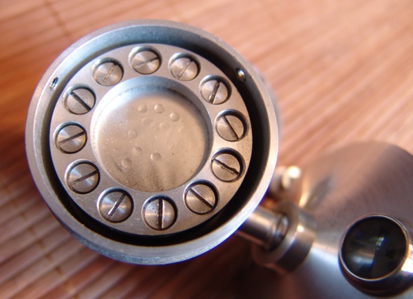
The bell…. is definitely cast aluminum. The inside plate at the connector end of the mic is also cast. The acorn nuts at the connector end fit a 7/16″ SAE wrench perfectly and the bolts with the wing nuts are US threads. 

Note the tiny piece of threaded stainless steel pipe bolted to the plate (to the left of the connector in the picture). I thought it might be a jack, but I think it is only a pipe. There is what appears to be a ground wire soldered to it inside the mic.


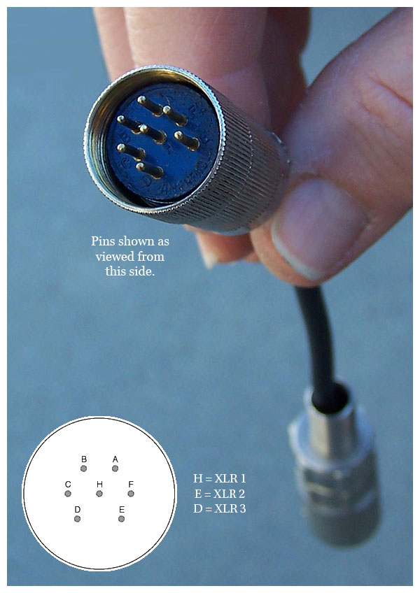
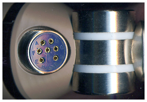
The number 13 etched beneath the bottom right connector blade corresponds with the number imprinted on the connector itself inside the mic.”

If any of our readers recognise this microphone or have any more information, we would love to hear from you.

Fi-Cord FC1200A tube microphone

This nice Fi-Cord 1200A tube microphone arrived without a power supply… so we built a new one!

The problem with these mics is that they are filled with resin, and it is almost impossible to get inside them. The mic has a Nuvista tube (like the AKG C28c) somewhere deep inside. Thankfully this one was working well so it just needed a new cable and an Xaudia custom power supply….

These mics were designed and built by Calrec, so it should be no surprise that they sound really good! There is a bit more information about Calrec Fi-Cord mics at Saturn Sound.

Thanks to Santiago Ramos

Thiele Microphones schematics and documents

Thiele, of Liepzig, were one of several manufacturers of tube condenser microphones in post-war Germany, although they are less well known than Neumann, Gefell and Schoeps. Thiele microphones also appeared under the Elektro-Medizin and Wetzel brands.

Thiele M4 microphone

The Thiele M1 (cardioid) and M4 (cardioid and omni) are great looking microphones but feature some frankly bizarre design decisions, most notably the placing of the tube directly behind the capsule, which interferes with the rear pickup whilst simultaneously cooking the PVC on the rear capsule. Of course the manufacturers would never have expected that we would be picking up these mics sixty years on and trying to record with them.

Inside a Thiele M4

In addition, the power supply was built into the base of the mic which can lead to hum issues despite the on-board potentiometer that acts as a ‘null’. This also means that the mic has two cables running from it – one for power and one for audio. Both mics use two-stage head amplifiers based around an ECC83 tube, and both have unbalanced outputs. Here are the official schematics for the M1 and M4 mics.

Thiele M4 microphone circuit

Thiele M1c tube microphone circuit

The M5 seems to have been the ‘Studio’ version, with an external power supply and output transformer for balanced low impedance operation. I haven’t seen a factory schematic for the M5, but this is a drawing that I traced out from a specimen on the bench.

Thiele M5 microphone, inside and out.

Here are some original sales and technical documents from Thiele, in  German.

Thiele sales brochure for M1 and M4

Elektro-Medizin M4 technical document

Elektro-Medizin M4 & M5 product sheet

Many thanks to the Microphone Online Museum for kindly sharing the documents and schematics.

“Big Al” – old German bottle mic

Big old German bottle microphone (flaschenmikrofon)

This time-capsule condition, stunning bottle mic is a recent ebay find, but we know very little about it! So, if you recognise this one, or have any further information, please get in touch.

In looks, this is very much in the style of an RFT CM7049 or a Neumann CMV3, but doesn’t match any of the models that I am aware of by those manufacturers. The mic stands around 320 mm tall by 80 mm diameter, and is beautifully machined from aluminium, so we’ll call him ‘Big Al’.

The bottom bell is secured by two thumbnuts, which make access to the tube and battery compartment very easy.

The capsule is held in place by a clamping ring with 12 screws, and the diaphragm looks to be either nickel, or some kind of metallised film. It is not possible to get the capsule out of the head without removing these screws – not something I really want to be doing. It is even possible to work out the backplate hole pattern from the dents in the diaphragm.

Bottle microphone capsule

The tube is a Telefunken DAF11 which dates back to the 1940s. I haven’t met one of these before, but the datasheet is available at Frank’s, and shows it to be a diode and pentode in the same shell, with a common heater & cathode.

DAF11 tube

The diode part is not used in this mic. The heater supply is a modest 1.2V at 50 mA, and is designed to run from a battery cell.

DAF11 bottle mic schematic
I traced out the circuit – the heater supply does indeed come from a battery, and there is a space inside the mic for a large cell. The switch on the top of the mic breaks the filament supply, saving battery power and (eventually) muting the mic, and there is a Neumann / RFT style indicator. in the top.
The capacitors in the rectangular metal cans are not labelled, but each can contains a pair of caps with a common negative terminal. On the bench, all four caps measure 1.0 ± 0.2 uF, and the different can sizes must reflect different voltage ratings.
There is no grid resistor present in the mic – either it has been removed for some reason, or the design relies on grid leak to set the bias.
Update 7/12/2011
We had a nice little discussion about this mic over at GroupDIY.

Microphone of the month – Old Czech tube mic: Tesla?

This is the first ‘Microphone of the Month’ blog, featuring classic or unusual microphones. Hopefully I’ll manage to find time each month for this!

This old Czech tube microphone – a recent ebay find – may well have been made by Tesla. The capsule is connected using a connector that can also be found on old Tesla and Phillips microphones. Some of the capacitors are also made by Tesla, who were a large state owned electronics company in communist Czechoslovakia.
The ‘Tesla’ looks very much like an imitation of the Neumann / Gefell CMV563 bottle mic. In fact the microphone is smaller in diameter than the CMV, has no output transformer and has an unbalanced output. Like the CMV, the capsule may be swapped, and presumably other polar patterns were available. This one is marked with a red circle, which probably means omnidirectional. (I have yet to test the capsule).
The amplifier is a very simple grounded cathode amplifier, based around a Soviet 6Ж1Л (6Z1P) tube, which is a small signal pentode similar to EF95. These are also found in some Lomo and Oktava microphones, including the Lomo 19a9 and Oktava MKL2500.

Without the original power supply we can only speculate on the operating voltages. However, a B+ supply of 90V would be a good place for experiments to start – this would give a voltage on the capsule of around 60, and a sensible current through the tube circuit.

Tube mic circuits – Connecting the capsule 2

Last week’s technical article talked about different methods of connecting a condenser capsule to the grid of a tube amplifier, in order to build a tube mic. In this part we consider how to connect a capsule with two diaphragms in order to get a multi-pattern mic.

First let’s examine the different pickup patterns available. There are three extremes: Omni, where the microphone hears sounds equally in all directions.  Cardioid (heart shaped*), where sensitivity is greatest in the direction in which the microphone is pointing, falling off to a null point behind. And Figure-of-Eight, with equal (but opposite) pickup in front and behind, and null pickup to the sides.  To complicate things further, the pickup pattern may depend upon the frequency, and some mics will have good directionality at higher frequencies, but become less directional as the frequency drops.

But what if we want a microphone with selectable pattern? This can be achieved by arranging a pair of cardioid capsules back-to-back, and combining there signals in different ways. We’ll call these capsules front and back, although of course they could be pointing in any direction. If we require a cardioid signal, we just take the front capsule and for omnidirectional pickup, we mix both signals equally. If we want figure of eight, we subtract the output of the rear from the front: where the signals overlap at the sides of the microphone, they cancel each other out producing null points. Other patterns such as hyper-cardioid and super-cardioid may be considered as in-between positions of these extremes.

So, what is the best way to achieve this practically in our hypothetical tube microphone? Two of the earliest commercial mics with more than one pattern were the Neumann U47, which offered cardioid and omni, and the U48, with cardioid & fig. 8. Let’s look at the U47, as this is probably the simplest way to combine the two capsules.

In the U47 the front diaphragm is grounded through a 100 Meg grid resistor, and the backplate of the microphone’s dual diaphragm is polarised with about 60V, providing the potential difference required. The rear diaphragm is connected to a switch. When the switch is open, the rear capsule is left floating and only the front cardioid diaphragm is active. When the switch is closed, the rear capsule adds its contribution to the front, making an omnidirectional microphone.

What about the U48? We have seen above that if we require figure of 8 instead of omnidirectional, we must subtract, rather than add, the sounds from the rear. To do this we must invert the polarity of the rear diaphragm by reversing its relative charge. So, rather than grounding the rear diaphragm, we must raise the potential by 60V** above the backplate, and 120V above the front capsule! This is easily achieved by using the HT supply to the anode of the tube, but creates another problem. We can’t simply connect the two diaphragms because they are now at different potentials, and so a blocking capacitor must be used. The circuit looks like this:

Finally, to make the microphone have variable pattern, we simply need to make a supply that is adjustable from 0V to 120V, and apply that to the backplate. Alternatively, the signal may be taken from the backplate, through a capacitor to the tube grid.  The Neumann-Gefell UM57 does it exactly this way, with the pattern selector in the power supply.

*Really more kidney shaped, and in some languages this is the word used.
**  In fact the U48 operates around 50V / 100V.

Further reading: The G7 page at Gyraf.dk

Tube mic circuits – Connecting the capsule part 1.

Even in the simplest of tube microphone circuits, there are different approaches to connecting the microphone capsule to the tube. Let’s use a single-sided microphone capsule as our starting point.

The capsule behaves as a variable capacitor, changing its capacitance in response to changes in air pressure (i.e. sound). In order to generate a signal, the capsule needs to be polarised by some voltage, creating a difference in potential between the diaphragm and the back plate. This is the first decision that needs to be made – should the polarising voltage be applied to the diaphragm or the capsule backplate?

In the circuit shown on the left, the backplate of the microphone is polarised at 60V, which is obtained from the B+ supply, via a resistive divider and a small capacitor to stabilise and filter the polarising voltage. The membrane is connected directly to the tube grid, and a high value resistor (Rg, typically 100 kΩ to 1000 kΩ) connects both the grid and the membrane to ground. We have our potential difference across the membrane, and the sensitivity of the mic may be adjusted by increasing and decreasing the polarisation voltage. As the capacitance of the capsule changes in response to sound, a tiny current will flow through Rg, and this signal is amplified by the tube.

An example of this arrangement may be seen in the Neumann Gefell M582.

In some cases the grid resistor may be omitted. In the circuit below, which appeared in an article in Tape Op magazine by Dave Royer, the capsule diaphragm is grounded by grid leakage rather than a ‘real’ resistor. It works perfectly.

This simple arrangement is not possible when the capsule backplate is mechanically (and electrically) connected to the body of the microphone. In this case the diaphragm must be polarised directly.

However, having a voltage of around 60V on the tube grid this would adversely change the operating points of the tube circuit, and so a capacitor must be used to block the DC voltage (left). Some listeners claim to hear the difference between different types of capacitors, and so normally a very high quality type should be used in this position. An additional high value polarising resistor is also required, otherwise the high impedance audio signal would be attenuated through the stabilisation cap.

An example of this method of connection is the Neumann-Gefell CMV563, which is designed to be used with bayonette style capsules such as the M7, M8 and M9.

Sometimes it is the membrane which is connected directly to the body, such as in this Teladi K120. The approach is the same as the circuit above.

In my next post I’ll consider how to connect mic capsules with two membranes, and how to combine them to generate different polar patterns.

Unknown German Prototype Tube Microphone – ‘The Unbekannt”

Unknown German tube microphone

Here is a recent Ebay find. It’s an unbranded tube microphone, and judging from the components probably from the 1960s, in what was formerly West Germany. We’ve called it the ‘Unbekannt’, which is simply German for ‘unknown’. The amplifier circuit is a 3 stage unbalanced transformerless design, using EF40 pentode and an ECC81 twin triode. The final stage is a cathode follower.

The schematic is here.

As is so often the case, the microphone has been separated from the original power supply, so it is not possible to say what the exact operating voltages would have been. However, the voltage divider for the capsule polarisation may give us a clue – 2 Meg and 400K would be a simple way of using a 240V supply to put 40V on the capsule.

The metalwork is nicely done, and is comparable to Reissmann, Thiele and Teladi microphones of similar age. It seems too well constructed to be a DIY mic, but the oddball range of parts makes us think that it is some prototype from one of the microphone makers of the era.

The capsule is quite unusual, but sadly is missing a diaphragm at the moment. It uses springs and screws to adjust the tension and space to the back plate, so this can be adjusted after installation. We’ll try to get that up and running very soon so we can see what it sounds like!

Thiele microphone brochure

Thiele M5 tube microphone
Here’s a scan of a short advertising document for Thiele M4 and M5 (photo to the left) tube microphones. 

Theile sales document
Note how expensive the microphones were at the time – 500 and 600 Deutchmarks. For reference, between 1950 and 1960, 4 Deutchmarks approximately equalled 1 US dollar.

Syncron AU7A microphones Part 2

Last time I wrote about a pair of Syncron AU7A microphones. The capsules were in good condition, but the batteries had leaked, causing corrosion and damage to the circuit. For one of these mics I decided to fit a tube circuit based on a 6205 subminiature tube (5840* would do just as well or better)**.

Tube modified Syncron microphone circuit, 6V regulated heater supply omitted.

The Syncron capsule operates happily between about 40V and 60V, and a simple voltage divider was used to supply the backplate with a suitable polarising voltage. As the capsule is cardioid only, the circuit can be made as simple as possible, and there is no need for a capacitor between the diaphragm and the tube grid.

With a little creative hacking I was able to reuse the circuit board to construct a valve circuit, which avoids damaging the microphone further. Although physically larger, the tube sits where the transistor was (I even used the same PCB pads as the FET), and there is room on the underside of the board for a couple of capacitors. An added bonus is that the original transformer is quite suitable for use in a tube circuit, and was rewired in 10:1 configuration. The rest of the circuit – 5 resistors and another cap – fit on the ‘wrong’ side of the board in the cavity below the capsule housing. Then it is a simple case of wiring the connector to the circuit and connecting the capsule, taking care not to damage the diaphragm.

One thing to look out for with this arrangement is that the amphenol cable plug & connector on the microphone are the reverse of the normal gender, which means that there can be 110V DC on the exposed pins. Consequently care must be taken to connect the microphone before the power supply is turned on, otherwise a short sharp shock can happen. Of course this isn’t really an acceptable acceptable solution from a safety point of view.
In practice the microphone works very nicely and is suitably quiet for recording vocals. We tracked some female vocals with it yesterday and it performed very well in that application.
Meanwhile, I have managed to track down some 22V batteries from Farnell, which should be suitable for the capsule polarisation, so I’ll attempt to restore the second mic to its original state. More on that soon.
** With hindsight the 5840 may be a better bet as there is an internal connection between the cathode and grid 3. This allows you to cut off two of the leads, which means using up one less precious pad on the circuit board inside – space is tight!
**Readers familiar with the ‘Royer’ tube circuit will recognise the topology, although a few of the component values are different.

Xaudia blog post on phantom power for these mics.

Neumann Gefell UM57 experiments

Lately I’ve had the opportunity to play around with several vintage Neumann Gefell tube microphones – a CMV563 (below with UM70 capsule) , a M582 and a pair of UM57s.

These all have broadly similar circuits, with a EC92 tube and transformer coupled feedback. The UM57 is configured for different polar patterns, whereas with the CMV563 and M582 you have to swap the capsule. There are other differences – the schematics are shown here.

One particularly common fault with examples of these microphones is that the original electrolytic output capacitor can dry out with age. This is by no means always the case, and the capacitor in the UM57 on the left above was in perfect condition after nearly 50 years!  The one on the right has been replaced with an orange modern metalised film capacitor.

So what is the effect of ageing of this capacitor? As the electrolyte dries out, the absolute value of the capacitance drops, which will affect the frequency response of the valve amplifier inside the microphone. To simulate this, a capacitance decade box was wired in place of the output capacitor (C3), and the chart below shows how the frequency response changes as the capacitance decreases in 0.2 uF steps.*

Part of the circuit is shown inset within the chart. Although intuitively we expect the smaller capacitor to give us less bottom end, the network of the capacitor, transformer primary winding and resistor acts as a resonant filter, producing a peak in the bass region just above a sharp drop off. The human ear can perceive this as more bass – although not necessarily in a good way: the microphone may seem muddy or lack clarity.

So, having a good quality capacitor here is vital, and the value of this can be used to tweak the bass response if desired. Of course this analysis is just for the tube circuit inside the mic and does not consider the effects of ageing on the capsule itself – that’s a story for another day.

SJT Feb 2010

* Measured using a swept-sine wave from 1Hz to 48KHz.

G7 microphone

Jakob Erland’s Gyraf G7 DIY tube mic project has proved one of the most popular microphone projects. Several years ago I built a pair of these from scratch, and have since built several variations using different tubes, transformers etc. Below are a few notes on the project.

1. Using a single sided capsule

When using a single sided capsule, the circuit can be simplified somewhat and several parts omitted. The capsule may be wired straight to the tube grid, avoiding use of a coupling cap. Note that this affects the polarity of the mic, so reverse the output wires and be sure to check against an SM57 or similar know microphone. In this arrangement, the backplate polarisation resistor can be lower than 1 gig.

2. Some measured voltages:

I built a version of the microphone by etching Gyraf’s layout. Wired it up and checked some voltages – and found that the supply is rather low under load. I got about 176 Volts without the mic connected, and was down to 136 V with the mic in the loop. Heater supply dropped from 6.3V (set whilst unloaded) to 6.08V. Here are some voltages for reference.

3. Better matching of the capsule polarisation voltages.

Note in the diagram above that one side of the capsule has a slightly higher voltage than the other – no problem in omni or cardioid but noticeable in figure8 mode when recording Blumlein pairs. Here’s a quick fix!