The 1970s saw a mass extinction of British companies that produced ribbon microphones.

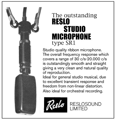
At the start of the 1960s there were at least seven significant and well established makers of ribbon microphones in the United Kingdom: Cadenza; Film Industries, Grampian, Lustraphone, Reslosound, ST&C, and Tannoy. Some of these companies like Reslo and ST&C had been in the business of producing microphones since the 1930s, yet by 1980 all seven had either ceased trading, sold their interests, or abandoned the market to focus on other products.
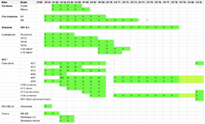
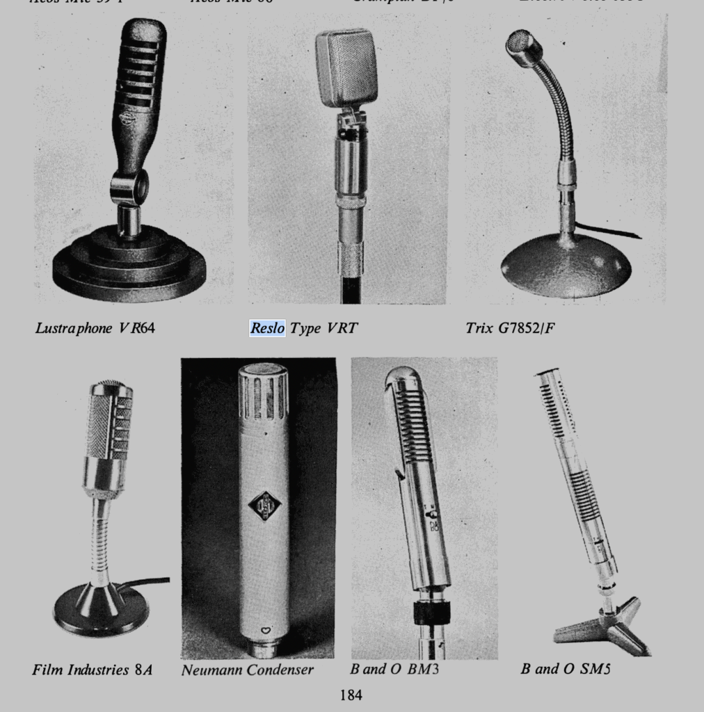
Tannoy stopped making ribbon mics in the early 1960s but continued to produce speakers and public address systems with such success that they became a household name – synonymous with unintelligible announcements at railway stations throughout Britain. SimonSound, who made the Cadenza microphones, disappeared in 1967. Perhaps the booming home recording market was already saturated at this point, and Cadenza was undoubtedly had the weakest design – evolutionary forces dictated that it would not survive. Similarly, Lustraphone had to all intents and purposed ceased making ribbon mics by 1971 – some new models such as their mythical 4-50 model were promoted but never appeared, and the company had vanished completely by 1973. Film Industries soon followed in around 1974 – their M8 models had been sold unchanged since the 1950s. Reslosound thrashed around for a few years, spitting out various new dynamic models, a new logo and even a condenser microphone. They finally ceased trading in 1978. Grampian hung around for another year before extinction.
So what happened? The British economy faced severe challenges in the mid 1970s, which led to a deep recession. Oil prices were sky high due to conflict in the Middle East, which was compounded by the Miners strike. This led to rampant inflation, power cuts, and a three day week for many workers to save electricity. The knock-on effects of this were high unemployment and reduces consumer spending.* It took nearly four years for the UK’s GDP to recover back to pre-1973 levels.
Arguably, some British manufacturers had not invested sufficiently in product development and were still selling the same technology that they had developed in the late 50s or early 60s. For example Film Industries M8, Lustraphone VR64, Reslo RB and Grampian GR1 were all essentially unchanged from 1960 through into the early 1970s. Meanwhile, new imported models from Shure, Neumann, Beyer and others were smaller, lighter and had better signal to noise and frequency response. And these new mics came with standard XLR or DIN plugs, which meant that the user did not need a different cable for every microphone. This combination of recession, reduced consumer confidence, and high quality imports squeezed the last breath out of the British ribbon microphone industries.
Did ST&C see this coming? They sold their microphone division to ITT in 1971, and then on to Coles Engineering in April 1974. Coles are still making the classic 4038 and other microphones to this day. Perhaps their focus on professional studio and broadcast rather than home taping made them more secure than others, and their contracts to provide the 4038 and commentator mics to the BBC surely helped.
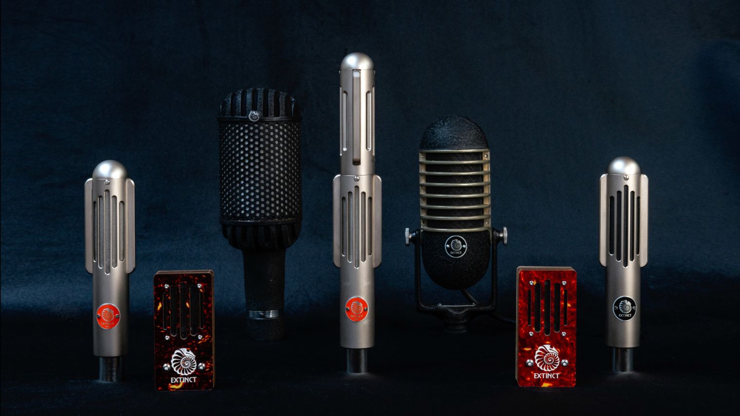
There has been a resurgence in ribbon microphone technology since the late 1990s. We started Extinct Audio in 2017, and are (perhaps) the first new company to make ribbon microphones in England since the 1970s. I guess we had better keep innovating – you never know when the comet is coming for you!
*Yes we are still talking about 1975 and not 2025!