… when you drop a Cadenza mic on a concrete floor.

Oops.
… when you drop a Cadenza mic on a concrete floor.
Here is a UK patent by Eric Thompson of Simon Equipment Ltd, from 1959, that relates to the Cadenza ribbon microphone: Cadenza Patent
 |
| Drawing from patent for Cadenza microphone |
The novelty in this patent is that the ribbon is fixed in the middle and clamped at either end. The inventors claim that this allows the two halves of the ribbon to be tuned to slightly different frequencies to give a flatter overall frequency response. I had suspected this for some time, but had never seen it written down! It also has the advantage of supporting the ribbon and giving it some protection against stretching. And here is a photo of the design in real life, from an earlier post.

This Ebay auction has solved a little mystery for me!
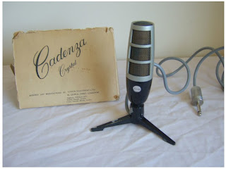 |
| Cadenza Crystal Microphone |
Cadenza was a British brand remembered primarily for their ‘Rocket’ ribbon microphones. They are still quite common, and I have repaired many of them in the course of my work.
 |
| Cadenza microphone with ribbon element |
Most of the Cadenza mics are grey or pale blue in colour, and have a removable stand. However, I have come across three or four of these mics with black bases and a fixed stand. These often have a crystal element rather than a ribbon motor, and I and speculated on their origins in a previous blog entry. When I first encountered one of these, I had thought that it was some kind of DIY ‘repair’ job, but having seen more than one, it seemed more likely that they came out of the factory this way.
 |
| Crystal element in a Cadenza body |
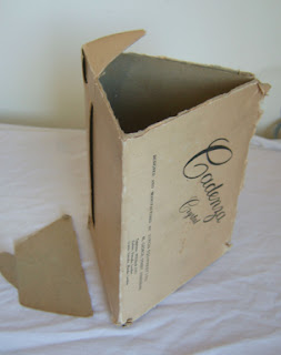
Until now I had never seen an advertisement, manual or box that could confirm the existence of a Cadenza Crystal microphone. The photos in the auction show the original packaging, marked ‘Cadenza Crystal. So this was indeed a Cadenza product, using the same body as the ribbon microphones.
I like the triangular box!
Thanks to Benchmark Collectibles for permission to use this photo.
Xaudia now supply drop-in upgrade transformers for Cadenza ribbon microphones.
 |
| Xaudia transformer (left) and original Cadenza tranny |

The transformer is supplied in a mumetal shielding can of the same dimensions as the original, and slots into the base of the mic below the motor assembly, as shown.
 |
| Cadenza on a stand! |
And here is a funky adapter that we made for a customer, to mount his Cadenza onto a normal mic stand. It recycles the plastic connector and locking ring from the original tripod mount.
 |
| Cadenza mic stand adapter |
*Or other impedance values on request.
I have come across a couple of Cadenza ribbon microphones recently that are not what they seem.

The microphones came from different sources, but both had been modified in the same way. The mods were performed long enough ago that the foam had started to disintegrate.
In both cases the ribbon element has been replaced by a dynamic element. and the mic stuffed with pink foam. Both mics are painted black with a silver top, and in both cases the stand adapter is fixed to the microphone rather than being removable.
|
| Rogue Cadenza with dynamic element |
There are clearly a few of these floating around. The stand modification looks well done, and I suppose it is just about possible that this was done at the factory, perhaps as a budget alternative to the ribbon mics, although I have not seen any documents to support that.
So, look out when buying old microphones – what you see is not always what you get.
Caveat Emptor!
Cadenza ribbon microphones are quite common, but there seem to be more microphones than there are connectors for them. The mics were originally supplied with an integrated stand & connector, which was ideal for desk recording, but not very effective for hanging over a drum kit.


The XLR has the added advantages of making a good earth connection, and also gives a way of mounting the mic on a stand as it can be slipped into a standard mic clip. I think elongating the base makes the look more elegant too.

Sometimes I see patterns or trends in what arrives on the bench. A year ago it was RCA 74s, and in spring 2011 it was Electrovoice ribbon mics. And then the summer brought Melodium 42bs. Of course these are just statistical anomalies or ‘blips’ in the random noise of what my customers send me to repair, but it does at least suggest ideas for the regular ‘Microphone of the Month’ column.
 |
| Cadenza microphone set with box, documents and stand |

 |
| Cadenza mic transformer under the knife |
From a technician’s viewpoint (i.e., my opinion :p), there are a some weak points in the design which all relate to the transformer. Firstly, the ribbon clamps are connected to the transformer simply by winding the wire under a nut and tightening it – really not a reliable long term approach. Secondly, the transformer wires are extremely thin, and half a century later the insulation becomes brittle and tends to break, with disastrous results. It is more common practice to use thick gauge wire for the fly-leads to the primary, to keep resistance and noise to a minimum. And finally, as these thin wires become old and oxidised, the mics become noisy.

 |
| Cadenza windings – primary (left), and 30 ohm output (right) |
