The Syncron AU7a was one of the earliest transistorised condenser microphones, and was also sold as the Fairchild F-22. It ran on four mercury batteries, which had a tendency to leak after a few decades and are now obsolete. Conversion to run on phantom power seems sensible, but the original circuit used a P-channel JFET and positive ground, which are not compatible with modern phantom power supplies. A new circuit and a new PCB will make things a lot simpler.
Syncron AU7a – circuit for P48 operation
We tried to stay close to the original philosophy, with a single transistor circuit which re-uses the Syncron transformer (above). The Syncron microphones that I have worked on did not use a source resistor bypass cap, but I had much better results with one in place. Dan Zellerman kindly supplied a version of the schematic which shows a 470 pF bypass cap, which was absent from my microphones.
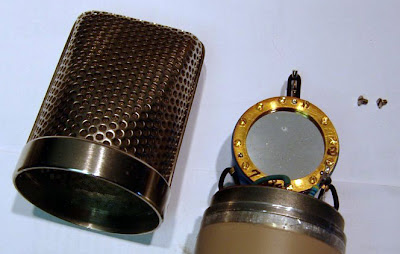
Working on these microphones is a bit of a pain because of the construction, and getting everything apart is the hardest part of this modification. The first job is to carefully remove the grill and capsule – put the capsule somewhere safe! The circuit is soldered inside a brass ring, and I needed to use a hot air gun and 80 watt iron to release that part. Some of the screws and mounting posts were also soldered in place. The transformer should be carefully removed, ready for re-use in the new circuit.
New circuit board for Syncron AU7a
The board is then populated and soldered with the exception of R5, which needs to be adjusted to bias the JFET. Either a J201 or 2N3819 will work here. To find a suitable value for the source resistor, I connected a decade box and messed around until the junction with R1 was at 12 volts. (For this example, the value if R5 was 5K1 ohms.). Another way is to hook it up to a scope and inject a sine wave, checking for highest gain and lowest distortion of the waveform, or you can even do it by ear with a pair of headphones. You’ll get a similar value either way. Larger capacitors go on the reverse side of the board, along with the transformer.
Transformer side of the circuit board.
Some of the clearance is tight and care should be taken to avoid shorting to the ring that surrounds the circuit. And at some point that ring needs to be soldered to ground to ensure good shielding. I used an 80 watt iron on the outside of the ring and fed the solder in from inside. Any flux residue and other crud should be cleaned from the board when all the soldering is done. A drop of glue between the ring and board would also be sensible – be sure to keep the glue away from the high impedance components.
New AU7a circuit in place awaiting clean-up.
The capsule can now carefully be put back in position and connected to the circuit, followed by reassembly of the rest of the microphone. This updated Syncron AU7a sounds very nice and with the new circuit it has a useable output level and the signal to noise is good. The output impedance is approximately 200 ohms with the transformer secondary windings wired in series or 50 ohms if wired in parallel.
Inside the AU7a with the new circuit board.
Below is a frequency sweep compared with a Sony C48 in cardioid mode. The updated Syncron has a similar output level to the Sony.
Syncron (green) and Sony C48 (blue) responses compared.
The Syncron Corporation are generally credited with launching the first transistorised capacitor microphone back in 1964 – the AU-7a, which was priced at $169.50 USD. In their own marketing, the manufacturer claimed to have built “the first microphone to successfully employ the Field Effect Transistor.” At the time, competitors such as Neumann were selling microphones with tube circuits such as the KM64 and U67 which required a separate power supply. The Syncron mics ran on batteries which saved lugging around an extra box and cable. I know we all love and revere the old Neumann tube microphones, but few would argue that they take longer to set up and warm up than a solid state mic.
Syncron-Vega S10 microphons
Following the AU7a, Syncron launched their second and final microphone, which was a rather nice small diaphragm condenser known as the S-10. By this time, the brand was owned by ‘Vega Electronics Corporation’ and had the address on their documents had moved from Connecticut to Santa Clara in California. The price for new microphones was $260.
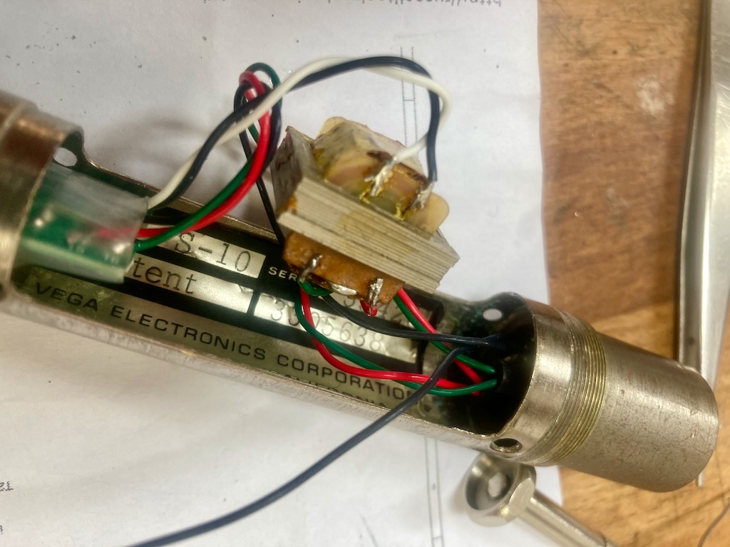
I was sent three S-10 microphones to clean, service and convert to phantom power for a customer. These mics were badged ‘Vega’./ Like the AU7As, they were designed to run on two obsolete batteries, and so being able to run on standard +48V would be make them much more useable.
Vega S-10 original circuit and transformer,
The mics were a bit of a mess. They had been stored damp at some point and showed corrosion inside and out. I wanted to be sympathetic to the original simple circuit They are a one-transistor circuit with an output transformer, much like a Neumann KM84, and so for the phantom conversion I decided to re-build with a KM84 style circuit, keeping the original transformers.
KM84 type circuit – Russell Technology board
With a bit of improvisation I was able to rebuild the circuits using circuit boards from Russell Technologies, utilising the space freed by removing the batteries to house the phantom circuit and the transformer. The circuit boards were originally designed as an upgrade for the AKG C480B, and uses a smaller transformer than the Vega. To accommodate the larger transformer I hacked off the end of the board and wired the transformer directly.
PCB from Russell Technologies – rear
S-10 with new PCB and transformer in place.
These microphones used a 4-pin XLR output. The fourth pin was used to make a connection to the battery within the plug of the connecting cable, which means that the batteries would not go flat so long as the microphone was unplugged between sessions. I swapped these for standard 3 pin XLRs of course.
Is four better than three? No.
Although we started with three microphones, one capsule was bad and one transformer was open circuit, so we have two nice condenser microphones, which are well balanced and sound good. The sound is a little less bright and a touch warmer than a KM84. I liked these microphones and was sorry to see them go home.
Syncron-Vega S-10 microphones
Update.
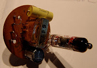
Jason at Crunch studios kindly shared the photo below and sound clip of his Vega S-10 in action.
Many thanks to Dan Zellman, a former Syncron employee, who sent in this schematic for the AU7A condenser microphone. This was the ‘last issue’ diagram.
In that post I had sketched out the schematic. I have since converted one for a customer to run on phantom power, and spotted a glaring error in the schematic. Here is the revised version…
The transistor is of course a P-channel JFET, and the battery polarity is reversed, giving a positive ground. The batteries are switched off when the plug is disconnected, and the routing through the plug makes tracing a little tricky – that was my excuse anyway.
All of this means that some small modifications are needed for phantom power use, because negative ground is by far easier to implement. Using an N-channel JFET makes things much more straightforward – something like this…
The ‘adjust’ resistor is tweaked for best response to a sine wave applied across the head amplifier, and in this case the result was around 1kΩ. JFETs can vary quite a lot, and it is sensible to adjust this individually for each mic.
I built a small breakout board to supply the required voltages from the phantom power. The board fits neatly in the battery compartment.
The “110K” is again adjusted on the bench to ensure that the voltage is correct under load.
There is one more thing to note – now we have switched to negative-ground and an n-channel device, the output cap needs to be flipped round.
Here’s a measured frequency response plot for the modified mic (the dips at around 150 Hz and 600 Hz are likely to be room modes)…
The microphone works perfectly, and it is nice to hear one brought back to life after all these years!
Last time I wrote about a pair of Syncron AU7A microphones. The capsules were in good condition, but the batteries had leaked, causing corrosion and damage to the circuit. For one of these mics I decided to fit a tube circuit based on a 6205 subminiature tube (5840* would do just as well or better)**.
The Syncron capsule operates happily between about 40V and 60V, and a simple voltage divider was used to supply the backplate with a suitable polarising voltage. As the capsule is cardioid only, the circuit can be made as simple as possible, and there is no need for a capacitor between the diaphragm and the tube grid.
With a little creative hacking I was able to reuse the circuit board to construct a valve circuit, which avoids damaging the microphone further. Although physically larger, the tube sits where the transistor was (I even used the same PCB pads as the FET), and there is room on the underside of the board for a couple of capacitors. An added bonus is that the original transformer is quite suitable for use in a tube circuit, and was rewired in 10:1 configuration. The rest of the circuit – 5 resistors and another cap – fit on the ‘wrong’ side of the board in the cavity below the capsule housing. Then it is a simple case of wiring the connector to the circuit and connecting the capsule, taking care not to damage the diaphragm.
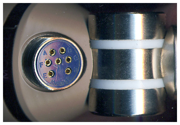
One thing to look out for with this arrangement is that the amphenol cable plug & connector on the microphone are the reverse of the normal gender, which means that there can be 110V DC on the exposed pins. Consequently care must be taken to connect the microphone before the power supply is turned on, otherwise a short sharp shock can happen. Of course this isn’t really an acceptable acceptable solution from a safety point of view.
In practice the microphone works very nicely and is suitably quiet for recording vocals. We tracked some female vocals with it yesterday and it performed very well in that application.
Meanwhile, I have managed to track down some 22V batteries from Farnell, which should be suitable for the capsule polarisation, so I’ll attempt to restore the second mic to its original state. More on that soon.
** With hindsight the 5840 may be a better bet as there is an internal connection between the cathode and grid 3. This allows you to cut off two of the leads, which means using up one less precious pad on the circuit board inside – space is tight!
**Readers familiar with the ‘Royer’ tube circuit will recognise the topology, although a few of the component values are different.
I was lucky enough to come across a pair of Syncron AU7A microphones (aka Fairchild F/22) on ebay. On arrival from the US I found that all the foam lining in the boxes had decomposed and spread black dust everywhere. Luckily the capsules appeared to be in fine condition, and the mics came with the original cables, so the should be a good chance of getting them back to working condition.
That’s easier said than done! The mics run on 4 batteries – 2 x 4.2V for the amplifier and 2 x 21V for the polarisation. Unfortunately, our microphones came complete with the original vintage batteries inside, which had inevitably leaked and caused corrosion throughout. The batteries are now pretty much unobtainable, so I used a bench voltage supply to simulate the batteries. Microphone number one gave a very weak and noisy (hiss) signal – I suspected the FET had somehow become contaminated by the battery acids. Mic 2 was slightly better, but certainly not something you could use as a serious recording tool.
These are reported to be the first commercially available FET microphone, and searching the internet didn’t throw up any schematics so I traced out the circuit, which is very very simple – capsule -> field effect transistor -> DC blocking cap -> transformer.
EDIT 21/9/2011 : please note that the schematic posted here contained errors. A revised version is here!
The transformer may be wired either for 200 or 50 ohms, and measurement showed it has a voltage ratio of 5:1 in series or 10:1 in parallel mode.
At this stage I needed to make a decision on how to get the best out of the microphone. More on that very soon, but for now here are some web links to Syncron information – there’s not a lot of it about!


