Swapping the motor in Beyer ribbon microphone.

Beyer sell replacement motors which allow repair of some of their microphones although the cost in the uk is rather high. Swapping the motor is a bit fiddly but can be done with patience and care. This is more or less how I do it, although the models do vary a bit and you may need to improvise.

Beyer M160 motor with rounded edges (left).

First note that Beyer motors may have round or square edges at the rear of the magnets. For many microphones this won’t matter, but the M160 grill will only accept motors with rounded magnets. In the picture above it looks rather crude like it was rasped down with a file! It is probably possible to make a square edged motor fit an M160 but the magnetic filings would surely wreck the ribbon,

Also worth mentioning is that Beyer M160 and 130 have two ribbons whereas M260s have a single ribbon.

To exchange the motor, first one needs to remove the socket and unsolder the connector and transformer.  The socket may be glued, screwed and/or pinned in place. Remove the screws or pin. If the socket does not slide out then it is glued and will need heating until the glue fails. Do this at your own risk! 

Then unsolder the socket, remove any rubber grommets and unsolder and remove the transformer.

Beyer M260 with socket and transformer removed

The next job is to pull the motor through the acoustic labyrinth but keep in mind that you will need to reverse the process in a few minutes. I usually solder an extra piece of wire into the end of the motor leads which will let me pull the new motor wires back into place.
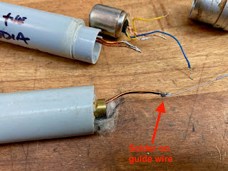
Remember to solder on a guide wire before you remove the motor

Once this is done you can pull the motor out and then unsolder, leaving the new wire in place.

Pull the motor and guide wire through the body

Unsolder the old motor and then reverse the process. Solder the new motor wires onto the guide wire, pull through the labyrinth and then unsolder. That parts is easier said than done because you are pulling some stiff wires around a bend that you can’t see. Reattach the transformer and socket. 

The only job left to do is to check the polarity of everything. Beyer do not always colour code their wires so you have to guess. Compare the microphone to a good modern mic. If your repaired Beyer is out of phase then simply reverse the wires at the XLR or din plug.

As a final warning, I have found that Beyerdynamic parts vary a lot and they do love to glue stuff together – why spend money on a screw or two when a tube of glue will do?  Be prepared for a certain amount of frustration and keep the swear-box to hand.

Synchron / Vega S10 Microphones

The Syncron Corporation are generally credited with launching the first transistorised capacitor microphone back in 1964 – the AU-7a, which was priced at $169.50 USD. In their own marketing, the manufacturer claimed to have built “the first microphone to successfully employ the Field Effect Transistor.” At the time, competitors such as Neumann were selling microphones with tube circuits such as the KM64 and U67 which required a separate power supply. The Syncron mics ran on batteries which saved lugging around an extra box and cable. I know we all love and revere the old Neumann tube microphones, but few would argue that they take longer to set up and warm up than a solid state mic.

Syncron-Vega S10 microphons

Following the AU7a, Syncron launched their second and final microphone, which was a rather nice small diaphragm condenser known as the S-10. By this time, the brand was owned by ‘Vega Electronics Corporation’ and had the address on their documents had moved from Connecticut to Santa Clara in California. The price for new microphones was $260.  

I was sent three S-10 microphones to clean, service and convert to phantom power for a customer. These mics were badged ‘Vega’./ Like the AU7As, they were designed to run on two obsolete batteries, and so being able to run on standard +48V would be make them much more useable.

Vega S-10 original circuit and transformer, 

The mics were a bit of a mess. They had been stored damp at some point and showed corrosion inside and out. I wanted to be sympathetic to the original simple circuit  They are a one-transistor circuit with an output transformer, much like a Neumann KM84, and so for the phantom conversion I decided to re-build with a KM84 style circuit, keeping the original transformers. 

KM84 type circuit – Russell Technology board

With a bit of improvisation I was able to rebuild the circuits using circuit boards from Russell Technologies, utilising the space freed by removing the batteries to house the phantom circuit and the transformer. The circuit boards were originally designed as an upgrade for the AKG C480B, and uses a smaller transformer than the Vega. To accommodate the larger transformer I hacked off the end of the board and wired the transformer directly.

PCB from Russell Technologies – rear

S-10 with new PCB and transformer in place.

These microphones used a 4-pin XLR output. The fourth pin was used to make a connection to the battery within the plug of the connecting cable, which means that the batteries would not go flat so long as the microphone was unplugged between sessions. I swapped these for standard 3 pin XLRs of course.

Is four better than three? No.

Although we started with three microphones, one capsule was bad and one transformer was open circuit, so we have two nice condenser microphones, which are well balanced and sound good. The sound is a little less bright and a touch warmer than a KM84. I liked these microphones and was sorry to see them go home.

Syncron-Vega S-10 microphones

Update.

 Jason at Crunch studios kindly shared the photo below and sound clip of his Vega S-10 in action.

Recording drums with the S-10 at Crunch Studios

Sound clip of the S10 in action:

You can read more about Syncron microphones at the Coutant website. 

Thanks to Jason Baldock at Crunch Studios