Reslo black and red label microphones

Disclaimer
Firstly let me say that this is a study in progress, and should by no means be taken as definitive. Hopefully we will eventually have a big enough data set to be able to speak with confidence, but it will take a while!

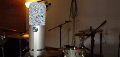
Red and black badges on Reslo ribbon mics.


Are black label Reslos better, or even different from red ones?

There is a rumour that occasionally appears on the internet concerning the relative merits of Reslosound RB microphones. Some of the mics have red labels, and others have black ones, which has led to speculation that the mics must be different, and one type must sound better than the other.

Normally it is stated that the black badged ones are better. Most rumours have some basis in fact, so let’s investigate!

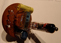
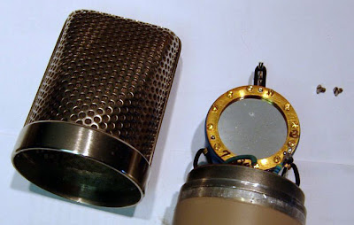
Reslosound RB microphone dissected

Over the past couple of years I have serviced around 50 Reslo mics, with both colours of badges. Here are some of my empirical observations…

1. The black ones are less common than the red ones, but they are by no means rare. I don’t have exact figures but perhaps 75% are red, and 25% black. I will be keeping note from now on!

Edit 29/11/2013: I wanted to correct this figure as I have seen it regurgitated on ebay a couple of times. Having seen a hundred or so more since I wrote this, I really can’t say that one is more rare than the other. I would probably guess that they are equally common.

2. There are at least three styles of red badges from different periods.

3. Some later mics (red and black) have a white plastic ribbon holder. The older mics have black bakelite holders. This should not affect the sound.

4. The transformers vary greatly in both looks and specs. This will affect the sound!

So, the only real differences between the red and black label microphones are the transformers (and possibly the state of the ribbons).

Recently, I had seven 30/50 ohm Reslo RB microphones on the bench, and I took the opportunity to examine the transformers. Although the basic construction is the same, the transformers are quite different in looks, and have different inductance values! Some have a striped core with two metals, the middle often being darker or rusty, suggesting a higher iron content. 

Reslo transformers (left to right) A, B, D, E, F

Impedance and resistance values
This is hardly a statistically significant data set, but here goes…

Black labels
A. Lp = 0.463 mH, Rp = 84 mΩ,  Ratio = 1:12, fc = 103 Hz (purple)
B. Lp = 0.434 mH, R= 56 mΩ,  Ratio = 1:12, fc = 110 Hz (pink)
C. Lp = 0.470 mH, R= 56 mΩ,  Ratio = 1:12, fc = 102Hz

H. Lp = 0.514 mH, R= 52 mΩ,  Ratio = 1:12, (purple)
I.   Lp = 0.441 mH, R= 45 mΩ,  Ratio = 1:12, (pink)

Red Labels
D. Lp = 0.533 mH, R= 52 mΩ,  Ratio = 1:12, fc = 89 Hz
E. Lp = 0.204 mH, R= 63 mΩ,  Ratio = 1:13, fc = 234 Hz
F. Lp = 0.214 mH, R= 63 mΩ,  Ratio = 1:13, fc = 223 Hz
G. Lp = 0.454 mH, R= 49 mΩ,  Ratio = 1:12, fc = 105 Hz

Where Lp is the inductance at 1KHz, and Rp the DC resistance of the primary winding.

The mics are supposed to be 30 to 50 ohms output, and so from the ratio we can estimate the impedance of the ribbon and transformer itself to be around 0.3 ohms. The ribbon impedance and transformer inductance form a high pass filter, and so we can calculate the frequency, fc, at which the bottom end response drops away.* This handy tool means that we don’t have to get out our calculators.

* It must be noted that the inductance of a metal core rises and frequency drops, so the cut-off frequencies will in reality be somewhat lower than these values. However, they should be comparable to one another.

What we can say for now, from our very limited data set, is that the three black label transformers, and two of the red ones, have substantially higher inductances and lower cut-off frequencies than the other two red ones. This difference in bass response is likely to be what some users hear as ‘better’. However, it cannot be said that a red label mic always has less bass response than a black one.

The two transformers with purple paint have higher values than the ones with pink paint!

My feeling is that the later Reslos have ‘better’ transformers than the early mics, and that the colour is more cosmetic than diagnostic. But I shall keep adding to this list as more Reslos come into the workshop, and it will be interesting to see what trends develop.

And finally, if you are reading this and once worked for Reslo (or Grampian), we would love to hear from you.

Update 12 May 2012…


In 1961 the BBC R&D group studied the Reslosound RB microphone and recommended that the transformer be replaced with one of higher inductance. It seems plausible that the later Reslos were revised to use a different transformer following that study. You can read the BBC report here.

Stewart Tavener, Xaudia, First posted 24 April 2012, Latest update 12 May 2012

Happy 2012!

2011 was a big year, with lots of changes.

Although we have been fixing ribbon mics for our own studio and a few customers for several years, 2011 was the first year that we went public and began to advertise the re-ribboning service. The mic repairs were moved to their own special room, with a dedicated testing chamber. The other big development was the acquisition of our Meteor coil winder, and the decision to do transformer repairs and re-winds in-house. This has vastly expanded the services that we can offer.

In 2011 we repaired some 186 microphones, along with a few guitars, amplifiers, reverbs, DI boxes and so on.

Xaudia – Distribution of microphones serviced in 2012, by manufacturer. 

The various models of Reslosound mics have been the most popular brand – there are still a lot of these around kicking around in Europe, and we serviced 37 of these in 2011. As one would expect, there were also quite a few RCA ribbon mics – 23 passed through our hands this year.

We would like to thank all of our customers for helping to make this such an excellent and fun year, and we look forward to even more exciting things in 2012.

Happy New Year!
Stewart & Jane
Xaudia.com

When good magnets go bad

This is the inside of a client’s Avantone dual ribbon microphone, which was in pretty bad shape.

The metal plating on the neodynium magnets has suffered a catastrophic failure, and in doing so has been pushed out, crunching the ribbons and covering the whole assembly with powdered neodynium alloy. Not good.

The cause of the failure is still a mystery – perhaps it could be due to a process failure in a batch of magnets, or maybe the mic was exposed to an excessively humid environment.

I have seen other mics with signs of flaking on the magnets, but nothing this serious. Neodynes are still a relatively new magnet technology, and how they will stand up to years of studio use and abuse remains to be seen.

Happily, we were able to bring the mic back to life by replacing the magnets and of course re-ribboning the mic.

Sony C38b stand mount repair

Here’s a fairly low-tech solution to a problem.


The Sony C38b is held by a yoke, and the stand mount contains a pair of rubber diaphragms which provide a little bit of shock absorption for the mic.

With time the rubber ion this one has perished, leaving the mic to flop around, rattle, and – worst of all – fall off the mic stand.

Here is how i fixed one with a strain relief rubber grommet, three rubber rings, and a jack plug bushing. The rubber rings are 23mm OD, 16 mm ID, and are the kind available (at least here in the UK) for fitting metal boxes for a ring mains, to stop the cables rubbing.  The grommet measured 14 mm OD, 5 mm ID, with a recessed ridge diameter of 9 mm, and is cut off at the bottom to fit.

Firstly, unscrew the large grey knurled nut and take the mount apart. All the old rubber needs to be cut away.  Then push the new strain relief grommet into the centre hole in the large grey knurled nut. Remove the bottom nut from the centre screw that is attached to the yoke, and push this into the centre of the grommet. It should look like this….

Then, pack the barrel of the mount with three rubber o-rings.

I then used a bushing from a Neutrik jack plug and inserted this into the centre.

Finally, push the re-rubbered yoke into the centre, and firmly hand-tighten the knurled nut. It should look like this.

The new assembly doesn’t give as much ‘bounce’ as the original, but it holds well, doesn’t rattle, and most importantly, it doesn’t fall off!

SJT

Syncron AU7a revisited – Phantom power

A while back I wrote about the Syncron AU7a FET condenser microphones, which are sometimes badged as the Fairchild F22.

In that post I had sketched out the schematic. I have since converted one for a customer to run on phantom power, and spotted a glaring error in the schematic. Here is the revised version…

The transistor is of course a P-channel JFET, and the battery polarity is reversed, giving a positive ground. The batteries are switched off when the plug is disconnected, and the routing through the plug makes tracing a little tricky – that was my excuse anyway.

All of this means that some small modifications are needed for phantom power use, because negative ground is by far easier to implement. Using an N-channel JFET makes things much more straightforward – something like this…

The ‘adjust’ resistor is tweaked for best response to a sine wave applied across the head amplifier, and in this case the result was around 1kΩ. JFETs can vary quite a lot, and it is sensible to adjust this individually for each mic.

I built a small breakout board to supply the required voltages from the phantom power. The board fits neatly in the battery compartment.

The “110K” is again adjusted on the bench to ensure that the voltage is correct under load.

There is one more thing to note – now we have switched to negative-ground and an n-channel device, the output cap needs to be flipped round.

Here’s a measured frequency response plot for the modified mic (the dips at around 150 Hz and 600 Hz are likely to be room modes)…

The microphone works perfectly, and it is nice to hear one brought back to life after all these years!

Strange things you find inside mics, part 2

A few months ago I wrote this blog post about the strange things that I had seen inside ribbon microphones. In those cases the ‘strange things’ in question were put in there deliberately by previous owners or techs trying to repair or improve the microphone.

Since then I have come across a couple of microphones which contained even weirder things – insects!

Before modern foams, felted wool was widely used in microphones for shock mounts, wind shields and the like. Unfortunately, moths love this stuff too.

Here’s an old STC4033. You can see the moth eggs on the lower block of green felt.
Worse still, one of the moths had become lodged behind the ribbon:
Moths also seem to like the wool lining and felt mounts on AKG D12s – here you can see the eggs and damage to the lining in the inside corner of the grill:
Anyway, I guess the lesson to be learned is that microphones should be stored in dry, clean places and not in the garage, or at the bottom of the wardrobe. 
😀
(thanks to Steve Parry  )

Thread Adapters for RCA, Sony and other microphones

RCA to modern mic stand thread adapter

A few months ago I was trying to find some thread adapters for a customer with an old RCA junior ribbon microphone, who wanted to use it with a modern standard 5/8″ microphone stand. Most suppliers were charging around $25 dollars, plus post and the inevitable import and handling duties.

So we decided to make some.

These fit most of the ‘big’ vintage RCA microphones, including the 44, 74b and 77 ranges, and also are perfect for Sony professional mics, including the C38b, FV300 and C48 microphones. They also fit Syncron AU7A / Fairchild F22 microphones, and several other American and Japanese microphones with a large thread.

Update:
These are now for sale on the Xaudia website priced at £6.00.

If you want one, please get in touch.

Strange things you find inside ribbon mics (part 1)

Microphone ribbons are generally made from very thin metal foil, and aluminium is the ideal material as it is very light but also very conductive. The output of the microphone is inversely proportional to mass, and so a thicker, heavier ribbon will give a lower output, and a thin light ribbon will be more sensitive. Many manufacturers use something typically around 0.0001 inch or 2 microns in thickness. The ribbon is also typically corrugated either along the full length to prevent lateral motion, or at the ends to give a ‘piston’ style of ribbon. Well, that is how it should be.

However, ultra-thin aluminium is hard to get hold of, and the non-specialist may be tempted to make repairs using materials that are more readily available. Here are some things I have found inside microphones masquerading as ribbons – needless to say they were all replaced with good quality aluminium foil of an appropriate thickness!

1. Cigarette Paper.

This microphone actually worked, to an extent! It at least made a sound. The ribbon was made from an old fag packet.
Cigarette packs used to come lined with paper-backed foil – I’ve never been a smoker so I don’t really know why, but I imagine for freshness or something. The foil is thin and already textured – it just needs to be separated from the paper. Actually this last part seems to be optional, and sometimes bits of paper are still attached, making the ribbon heavy and noisy.

1.b I’ve heard that chewing gum wrappers were also used for redneck ribbons, if you want a minty fresh microphone.

1.c Here’s a lovely example of cigarette paper being used for a ribbon in an old GEC microphone.

2. Kitchen Foil

Kitchen foil is easy to handle, yet much too thick to make a decent ribbon. But that doesn’t stop people trying. This is a common ebay trick… the ribbon looks in good condition, but when the mic arrives the output is low and sounds crunchy.

3. Sweet Wrappers

Plastic coated foil or metallised plastic, like that found in sweet wrappers is an interesting innovation, but is generally too heavy and has too high a resistance to make a decent ribbon. Also the plastic doesn’t conduct. This microphone gave almost no signal, and it isn’t hard to see why.

Fun with magnets and an Electrovoice V1 velocity ribbon mic

Here’s an early Electrovoice velocity ribbon mic, model V1. These are great looking microphones, but the early versions are rather crudely made and this one, like many others, suffered from low output due to weakened magnets.

Bob Crowley has a few things to say about these mics – not all of them nice!

The motor of this model is based on a single cylindrical permanent magnet, clamped to a pair of metal plates which make up the pole pieces of the assembly. Because of the positioning of the magnet, the magnetic field is uneven, with a significant difference in field between the top and bottom of the motor assembly. In our example we found that the field varied from around 700 gauss at the bottom to 1000 gauss at the strongest point. This is very low for a ribbon mic, and, along with the oxidised ribbon is responsible for a low, noisy output.

Fortunately, we have sourced some very powerful cylindrical N42 neodynium magnets of a suitable size and shape, which are a perfect replacement for the original weak magnet.

With the new magnet the field is increased by a factor of around four, to about 3000-3200 gauss, a much healthier figure which should lead to an increased output and much improved signal-to-noise performance.

Now it’s time to cut a new ribbon, reassemble the microphone, and do some listening tests. In the meantime, we made a rather attractive bracelet from some of the spare magnets.

Tube mic circuits – Connecting the capsule 2

Last week’s technical article talked about different methods of connecting a condenser capsule to the grid of a tube amplifier, in order to build a tube mic. In this part we consider how to connect a capsule with two diaphragms in order to get a multi-pattern mic.

First let’s examine the different pickup patterns available. There are three extremes: Omni, where the microphone hears sounds equally in all directions.  Cardioid (heart shaped*), where sensitivity is greatest in the direction in which the microphone is pointing, falling off to a null point behind. And Figure-of-Eight, with equal (but opposite) pickup in front and behind, and null pickup to the sides.  To complicate things further, the pickup pattern may depend upon the frequency, and some mics will have good directionality at higher frequencies, but become less directional as the frequency drops.

But what if we want a microphone with selectable pattern? This can be achieved by arranging a pair of cardioid capsules back-to-back, and combining there signals in different ways. We’ll call these capsules front and back, although of course they could be pointing in any direction. If we require a cardioid signal, we just take the front capsule and for omnidirectional pickup, we mix both signals equally. If we want figure of eight, we subtract the output of the rear from the front: where the signals overlap at the sides of the microphone, they cancel each other out producing null points. Other patterns such as hyper-cardioid and super-cardioid may be considered as in-between positions of these extremes.

So, what is the best way to achieve this practically in our hypothetical tube microphone? Two of the earliest commercial mics with more than one pattern were the Neumann U47, which offered cardioid and omni, and the U48, with cardioid & fig. 8. Let’s look at the U47, as this is probably the simplest way to combine the two capsules.

In the U47 the front diaphragm is grounded through a 100 Meg grid resistor, and the backplate of the microphone’s dual diaphragm is polarised with about 60V, providing the potential difference required. The rear diaphragm is connected to a switch. When the switch is open, the rear capsule is left floating and only the front cardioid diaphragm is active. When the switch is closed, the rear capsule adds its contribution to the front, making an omnidirectional microphone.

What about the U48? We have seen above that if we require figure of 8 instead of omnidirectional, we must subtract, rather than add, the sounds from the rear. To do this we must invert the polarity of the rear diaphragm by reversing its relative charge. So, rather than grounding the rear diaphragm, we must raise the potential by 60V** above the backplate, and 120V above the front capsule! This is easily achieved by using the HT supply to the anode of the tube, but creates another problem. We can’t simply connect the two diaphragms because they are now at different potentials, and so a blocking capacitor must be used. The circuit looks like this:

Finally, to make the microphone have variable pattern, we simply need to make a supply that is adjustable from 0V to 120V, and apply that to the backplate. Alternatively, the signal may be taken from the backplate, through a capacitor to the tube grid.  The Neumann-Gefell UM57 does it exactly this way, with the pattern selector in the power supply.

*Really more kidney shaped, and in some languages this is the word used.
**  In fact the U48 operates around 50V / 100V.

Further reading: The G7 page at Gyraf.dk

Tube mic circuits – Connecting the capsule part 1.

Even in the simplest of tube microphone circuits, there are different approaches to connecting the microphone capsule to the tube. Let’s use a single-sided microphone capsule as our starting point.

The capsule behaves as a variable capacitor, changing its capacitance in response to changes in air pressure (i.e. sound). In order to generate a signal, the capsule needs to be polarised by some voltage, creating a difference in potential between the diaphragm and the back plate. This is the first decision that needs to be made – should the polarising voltage be applied to the diaphragm or the capsule backplate?

In the circuit shown on the left, the backplate of the microphone is polarised at 60V, which is obtained from the B+ supply, via a resistive divider and a small capacitor to stabilise and filter the polarising voltage. The membrane is connected directly to the tube grid, and a high value resistor (Rg, typically 100 kΩ to 1000 kΩ) connects both the grid and the membrane to ground. We have our potential difference across the membrane, and the sensitivity of the mic may be adjusted by increasing and decreasing the polarisation voltage. As the capacitance of the capsule changes in response to sound, a tiny current will flow through Rg, and this signal is amplified by the tube.

An example of this arrangement may be seen in the Neumann Gefell M582.

In some cases the grid resistor may be omitted. In the circuit below, which appeared in an article in Tape Op magazine by Dave Royer, the capsule diaphragm is grounded by grid leakage rather than a ‘real’ resistor. It works perfectly.

This simple arrangement is not possible when the capsule backplate is mechanically (and electrically) connected to the body of the microphone. In this case the diaphragm must be polarised directly.

However, having a voltage of around 60V on the tube grid this would adversely change the operating points of the tube circuit, and so a capacitor must be used to block the DC voltage (left). Some listeners claim to hear the difference between different types of capacitors, and so normally a very high quality type should be used in this position. An additional high value polarising resistor is also required, otherwise the high impedance audio signal would be attenuated through the stabilisation cap.

An example of this method of connection is the Neumann-Gefell CMV563, which is designed to be used with bayonette style capsules such as the M7, M8 and M9.

Sometimes it is the membrane which is connected directly to the body, such as in this Teladi K120. The approach is the same as the circuit above.

In my next post I’ll consider how to connect mic capsules with two membranes, and how to combine them to generate different polar patterns.

Unknown German Prototype Tube Microphone – ‘The Unbekannt”

Unknown German tube microphone

Here is a recent Ebay find. It’s an unbranded tube microphone, and judging from the components probably from the 1960s, in what was formerly West Germany. We’ve called it the ‘Unbekannt’, which is simply German for ‘unknown’. The amplifier circuit is a 3 stage unbalanced transformerless design, using EF40 pentode and an ECC81 twin triode. The final stage is a cathode follower.

The schematic is here.

As is so often the case, the microphone has been separated from the original power supply, so it is not possible to say what the exact operating voltages would have been. However, the voltage divider for the capsule polarisation may give us a clue – 2 Meg and 400K would be a simple way of using a 240V supply to put 40V on the capsule.

The metalwork is nicely done, and is comparable to Reissmann, Thiele and Teladi microphones of similar age. It seems too well constructed to be a DIY mic, but the oddball range of parts makes us think that it is some prototype from one of the microphone makers of the era.

The capsule is quite unusual, but sadly is missing a diaphragm at the moment. It uses springs and screws to adjust the tension and space to the back plate, so this can be adjusted after installation. We’ll try to get that up and running very soon so we can see what it sounds like!

Syncron AU7A microphones Part 2

Last time I wrote about a pair of Syncron AU7A microphones. The capsules were in good condition, but the batteries had leaked, causing corrosion and damage to the circuit. For one of these mics I decided to fit a tube circuit based on a 6205 subminiature tube (5840* would do just as well or better)**.

Tube modified Syncron microphone circuit, 6V regulated heater supply omitted.

The Syncron capsule operates happily between about 40V and 60V, and a simple voltage divider was used to supply the backplate with a suitable polarising voltage. As the capsule is cardioid only, the circuit can be made as simple as possible, and there is no need for a capacitor between the diaphragm and the tube grid.

With a little creative hacking I was able to reuse the circuit board to construct a valve circuit, which avoids damaging the microphone further. Although physically larger, the tube sits where the transistor was (I even used the same PCB pads as the FET), and there is room on the underside of the board for a couple of capacitors. An added bonus is that the original transformer is quite suitable for use in a tube circuit, and was rewired in 10:1 configuration. The rest of the circuit – 5 resistors and another cap – fit on the ‘wrong’ side of the board in the cavity below the capsule housing. Then it is a simple case of wiring the connector to the circuit and connecting the capsule, taking care not to damage the diaphragm.

One thing to look out for with this arrangement is that the amphenol cable plug & connector on the microphone are the reverse of the normal gender, which means that there can be 110V DC on the exposed pins. Consequently care must be taken to connect the microphone before the power supply is turned on, otherwise a short sharp shock can happen. Of course this isn’t really an acceptable acceptable solution from a safety point of view.
In practice the microphone works very nicely and is suitably quiet for recording vocals. We tracked some female vocals with it yesterday and it performed very well in that application.
Meanwhile, I have managed to track down some 22V batteries from Farnell, which should be suitable for the capsule polarisation, so I’ll attempt to restore the second mic to its original state. More on that soon.
** With hindsight the 5840 may be a better bet as there is an internal connection between the cathode and grid 3. This allows you to cut off two of the leads, which means using up one less precious pad on the circuit board inside – space is tight!
**Readers familiar with the ‘Royer’ tube circuit will recognise the topology, although a few of the component values are different.

Xaudia blog post on phantom power for these mics.

Syncron AU7A (Fairchild F/22) microphones Part 1

I was lucky enough to come across a pair of Syncron AU7A microphones (aka Fairchild F/22) on ebay. On arrival from the US I found that all the foam lining in the boxes had decomposed and spread black dust everywhere. Luckily the capsules appeared to be in fine condition, and the mics came with the original cables, so the should be a good chance of getting them back to working condition.

That’s easier said than done! The mics run on 4 batteries – 2 x 4.2V for the amplifier and 2 x 21V for the polarisation. Unfortunately, our microphones came complete with the original vintage batteries inside, which had inevitably leaked and caused corrosion throughout. The batteries are now pretty much unobtainable, so I used a bench voltage supply to simulate the batteries. Microphone number one gave a very weak and noisy (hiss) signal – I suspected the FET had somehow become contaminated by the battery acids. Mic 2 was slightly better, but certainly not something you could use as a serious recording tool.
These are reported to be the first commercially available FET microphone, and searching the internet didn’t throw up any schematics so I traced out the circuit, which is very very simple – capsule -> field effect transistor -> DC blocking cap -> transformer.

EDIT 21/9/2011 : please note that the schematic posted here contained errors. A revised version is here!

The transformer may be wired either for 200 or 50 ohms, and measurement showed it has a voltage ratio of 5:1 in series or 10:1 in parallel mode.
At this stage I needed to make a decision on how to get the best out of the microphone. More on that very soon, but for now here are some web links to Syncron information – there’s not a lot of it about!

Neumann Gefell UM57 experiments

Lately I’ve had the opportunity to play around with several vintage Neumann Gefell tube microphones – a CMV563 (below with UM70 capsule) , a M582 and a pair of UM57s.

These all have broadly similar circuits, with a EC92 tube and transformer coupled feedback. The UM57 is configured for different polar patterns, whereas with the CMV563 and M582 you have to swap the capsule. There are other differences – the schematics are shown here.

One particularly common fault with examples of these microphones is that the original electrolytic output capacitor can dry out with age. This is by no means always the case, and the capacitor in the UM57 on the left above was in perfect condition after nearly 50 years!  The one on the right has been replaced with an orange modern metalised film capacitor.

So what is the effect of ageing of this capacitor? As the electrolyte dries out, the absolute value of the capacitance drops, which will affect the frequency response of the valve amplifier inside the microphone. To simulate this, a capacitance decade box was wired in place of the output capacitor (C3), and the chart below shows how the frequency response changes as the capacitance decreases in 0.2 uF steps.*

Part of the circuit is shown inset within the chart. Although intuitively we expect the smaller capacitor to give us less bottom end, the network of the capacitor, transformer primary winding and resistor acts as a resonant filter, producing a peak in the bass region just above a sharp drop off. The human ear can perceive this as more bass – although not necessarily in a good way: the microphone may seem muddy or lack clarity.

So, having a good quality capacitor here is vital, and the value of this can be used to tweak the bass response if desired. Of course this analysis is just for the tube circuit inside the mic and does not consider the effects of ageing on the capsule itself – that’s a story for another day.

SJT Feb 2010

* Measured using a swept-sine wave from 1Hz to 48KHz.

Recording with the Josephson C720

Back in August we were lucky enough to get our hands on a special edition Josephson C720 microphone for the studio, one of only 20 made in the first production run, and having lived with this for nearly half a year it’s probably about time we reviewed it.
josephson C720 microphone
The first thing you notice about the C720 is its size – this is one big mic, U47-big, and makes a big bold statement in the live room or vocal booth – it’s built like a tank and it definitely has that ‘wow’ factor which gets the artists talking.
The next thing that grabs your attention is its radical aluminium metal-foam headbasket, which looks like something you could scrub your pots and pans with. The non-periodic headbasket is actually designed to eliminate internal acoustic reflections and refraction of soundwaves, avoiding comb-filtering effects and so giving a more realistic recording.
The third thing you notice is that it has two XLR outputs. Like many condenser microphones, the capsule has dual diaphragms which can be combined in different combinations to give cardioid, omni, figure of eight patterns. Unlike most microphones, the two transducers have separate head amplifiers and separate outputs which means that the signals from opposite sides of the microphone can be recorded separately and mixed together, either in phase or with the polarity reversed, at a later stage. What this innovation means in practice is that you can pick the polar pattern after recording, which might be used to eliminate unwanted sound sources by rotating the null point of the microphone. Also, and more importantly in our studio use, with close-mic’ed sources such as vocals you can dial in more or less proximity effect, making a singer seem bigger, darker or lighter and brighter.
So what does it sound like? Possibly because of the lack of head basket comb filtering, and the facility to tune the pattern and proximity effect, this is a very versatile microphone. The one word that sprang to my mind in describing the sound, whichever pattern you pick, is ‘solid’.*
Another thing we’ve noticed is it sounds pretty damned good on pretty much anything you can throw at it. Because of it’s ability to handle high sound pressure levels and become a go-to mic for low end stuff, and is rock-solid on bass guitar and front of kick drum, but it’s just as handy on both male and female vocals – especially those with a tendency to get loud when they belt it out. Vocal recordings are up front, sound as they should, but without the top end brightness of, say, our TLM49.
Furthermore, it can be used for more radical effects by compressing or reverberating one side of the capsule only. For example, I had some interesting results on a male rock vocal by compressing the signal from the front capsule, mixing together with the phase reversed rear capsule, then compressing the sum of these. The effect was that as the vocals push harder, the relative amount of rear capsule included becomes greater giving it more of a hypercardioid pattern, balancing the tendency of the vocalist to step back from the mic when belting it out. With a bit of creativity the possibilities are endless.
Overall this is a brilliant, radical piece of thinking and and one of those bits of gear that comes into your life and is there to stay.
*After writing this I read another review of this mic which used exactly the same word – ‘solid’ – to sum up the sound.