 Here is our new pride and joy – a 1960’s AVO mkIII valve characteristic meter. It’s built like a tank, with wonderful vintage knobs and dials. And comes in handy for getting those amps and mics up and running.
07-01-2010
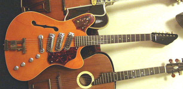 |
| Framus Television |
It is quite sad to think that the success of the big American guitar manufacturers (F–, G–, you know who you are!) led not only to some excellent instruments and high standards of construction, but also to the demise of several smaller builders of quality guitars. Cheap imports from the East added to the problem. One such victim was the German manufacturer Framus, who went bankrupt and ceased production at the end of the ’70s. (The company has since been reborn).
Framus made guitars of generally high quality with some interesting features. Here is a 1968 Framus Television semi-acoustic, the shape of which is clearly influenced by Fender’s Jaguar/Jazzmaster (or was it the other way round?) . It has a pleasing asymmetry, with a single f-hole (as far as we can tell, most Televisions had two), three pickups, and a tremolo. The headstock shape is whacky – like a big hand – but we like it. Colour of this one is a beautiful stained carrot-orange-yellow, rather like certain Gretschs – we think they call this ‘aniline yellow’. It has a laminate top and back.
This guitar arrived on the bench with toggle switches in place of the original sliders, as well as a couple of loose wires, which we of course replaced/fixed. The circuit is slightly unusual (which is why it is on this website at all!), so we’ve sketched a circuit diagram to help other owners.
 |
| Framus Television circuit |

The circuit consists of two parallel output stages each with volume and tone pots (marked T&V in the diagram) , which the player may use to switch between ‘rhythm’ and ‘lead’ settings. This approach predates the days when everyone has booster pedals on the floor, and similar systems are also found on Jaguars and Jazzmasters. In the ‘rhythm’ position, only the neck pickup is active. In the ‘lead’ position any combination of the three pickups may be switched on – the pickups in combination give some audible phase cancellation. There is also a bass cut filter switch. A summary of the switches:
S1 = Bridge pickup on/off
S2 = Middle pickup on/off
S3 = Neck pickup on/off
S4 = Bass cut (lead circuit only)
S5a = Sends neck pickup to rhythm or lead tone/volume circuit.
S5b = Switches between lead and rhythm tone/volume circuits.
As the tone and volume pots are tricky to remove and function well, they were not investigated or measured for value. I think they are just standard.
There’s a good chance that the circuit is similar to Strato Delux models of similar vintage, which also have up to 5 switches. Do let us know if you can confirm or deny this.

Jakob Erland’s Gyraf G7 DIY tube mic project has proved one of the most popular microphone projects. Several years ago I built a pair of these from scratch, and have since built several variations using different tubes, transformers etc. Below are a few notes on the project.
1. Using a single sided capsule

When using a single sided capsule, the circuit can be simplified somewhat and several parts omitted. The capsule may be wired straight to the tube grid, avoiding use of a coupling cap. Note that this affects the polarity of the mic, so reverse the output wires and be sure to check against an SM57 or similar know microphone. In this arrangement, the backplate polarisation resistor can be lower than 1 gig.
2. Some measured voltages:

I built a version of the microphone by etching Gyraf’s layout. Wired it up and checked some voltages – and found that the supply is rather low under load. I got about 176 Volts without the mic connected, and was down to 136 V with the mic in the loop. Heater supply dropped from 6.3V (set whilst unloaded) to 6.08V. Here are some voltages for reference.
3. Better matching of the capsule polarisation voltages.
Note in the diagram above that one side of the capsule has a slightly higher voltage than the other – no problem in omni or cardioid but noticeable in figure8 mode when recording Blumlein pairs. Here’s a quick fix!
