STC 4136 revisited

STC 4136 microphone

A long time ago I posted about the STC 4136 condenser microphone and how to modify it to work on standard 48V phantom power, using a small circuit built on perfboard.

STC 4136 microphone, in pieces.

I had another opportunity to work on one of these microphones. This one was a challenge as it had no circuit inside at all, just the capsule and bodywork, although that also gave free scope to start from scratch.

STC 4136 microphone capsule.

Space is tight in this microphone, but with a careful layout and small components everything will fit neatly. My solution for this one was to fit a small KM84 circuit and Neutrik NTE10/3  transformer. This transformer performs well, does not break the bank, and can be squeezed into tiny spaces where nothing else will go. 

New circuit board and transformer

This time I commissioned a printed circuit board rather than working on perfboard, which does save time and look more professional. The board will be useful for other projects too – I have a handful of other small microphones which would benefit from updated, lower noise circuits.

Made in England

Thanks to Robert at Russell Technologies for the board layout and advice.

Sony Condenser Microphone Evolution – C37, C38, C48 and friends

Sony made a series of excellent large diaphragm condenser microphones, some of which have become studio classics. The earliest production model was the C37A, a tube microphone which may or may not have been used by Frank Sinatra – he has certainly been pictured with one – and it was definitely used to record the voices of Bugs Bunny and Daffy Duck. It has become sufficiently iconic for at least two clones to appear, made by Mojave and Tonelux.

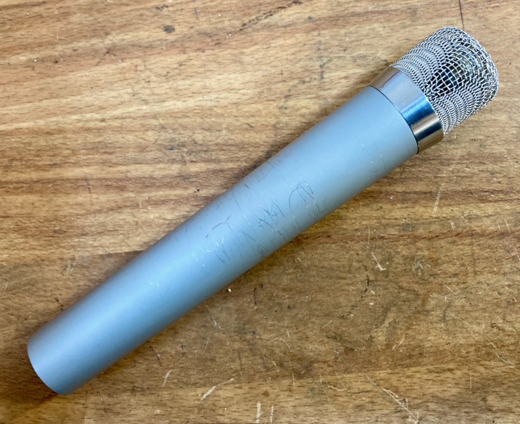
On test – Sony C37p, C38b, C48 and C450

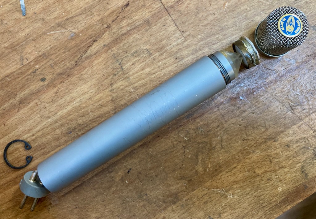
The C37P is the FET version of the C37, and is claimed to be one of the earliest production transistorised condenser microphones, although that honour is generally given to the Syncron AU7a. The C37p was followed by the C37Fet, and the C38 models. All of these microphones feature an unusual capsule design with an internal vent, which could be moved with a screwdriver from the rear of the microphone, changing the pattern from cardioid to omnidirectional. A very similar capsule is now made by Josephson Engineering, which is used in some of their own models and also rumoured to be supplied to other brands.

Sony C37 capsule – front
I am a big fan of the C38p and for the past 20 years have almost always used one for recording on my own guitar amplifier, often alongside a Shure 57 or whatever else is free after setting up for the rest of the band. The Achilles’ heel of this design is that the mechanism can become difficult to turn, and many the C37s and C38s are stuck in the cardioid position. For many users that is not a problem.

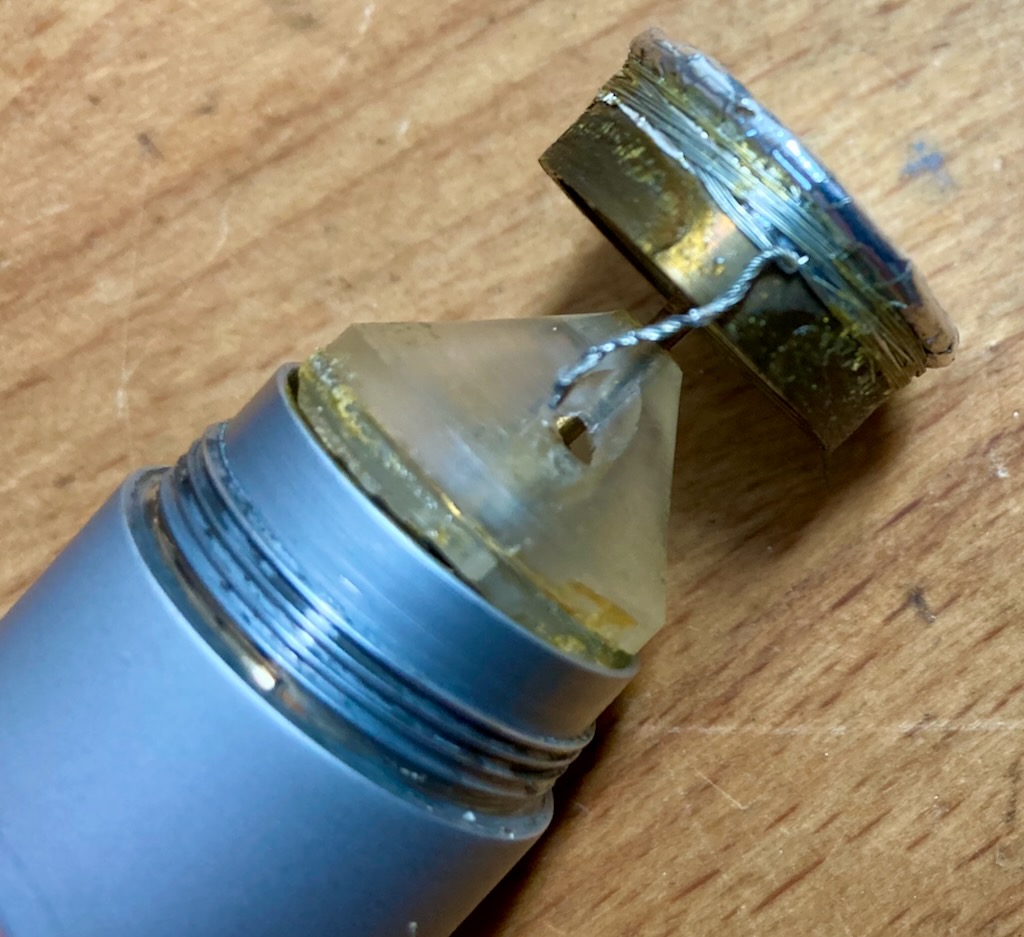
Sony C37 capsule – rear view

The later C48 and C800 models use a different dual sided capsule with centre terminals, which looks similar to those used widely by Neumann (and almost everyone else.) The C48 is a versatile microphone with three available patterns, bass cut and pad switches. 

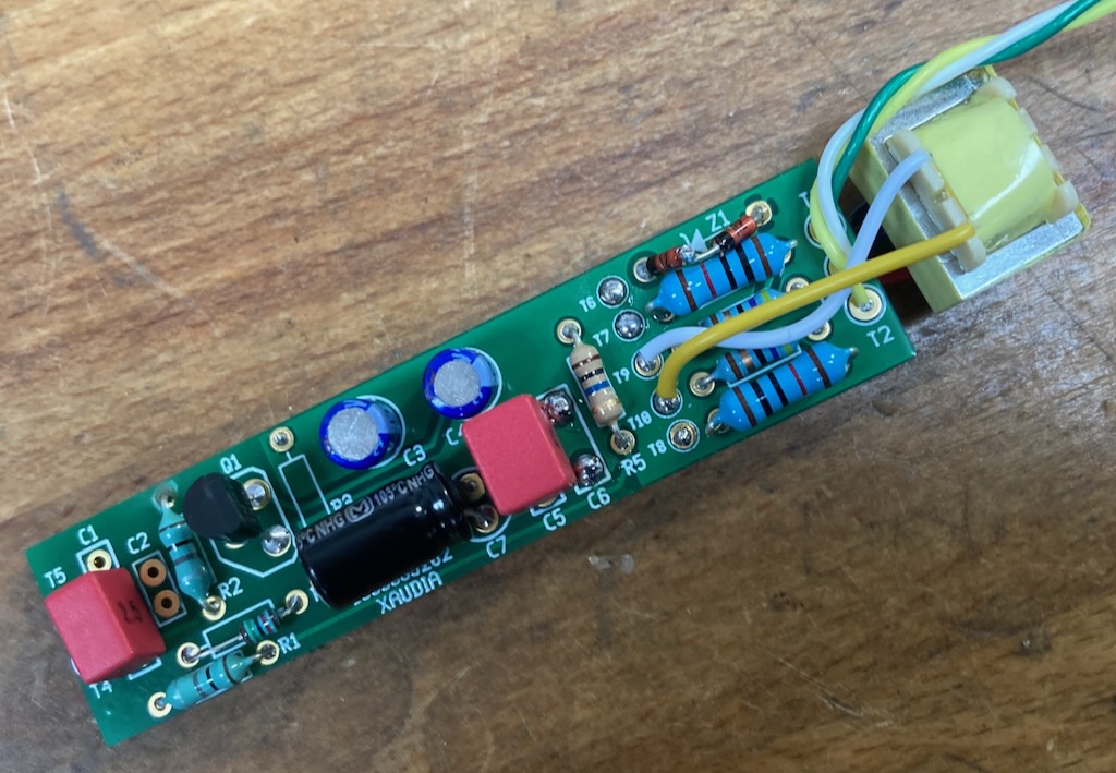
Both the C38 and C48 models can run on 9V batteries and use a DC converter inside the microphone to generate the polarisation voltage for the capsule. These converters are tricky to repair when they fail.

Sam Inglis & I recently had an opportunity to compare a few Sony condenser microphones to see how they had evolved over time. On the day of testing we had access to a pair of C37p, one C38b, a C48 and a C450. In addition we looked at a Josephson C705 for comparison.

By comparing the microphones we hope to discover how these Sony LDC mics compare and are the new ones better than the old ones (or vice versa)? Does the capsule hold the key to the Sony sound, if there is indeed such a thing? And are the new capsules from Josephson good copies of the old Sony C37/C38 capsules?

As usual, the frequency sweeps are good for comparison purposes but are run in a small booth and should not be considered absolute measurements. The reference microphone is omnidirectional, which can cause a few inaccuracies when testing cardioid transducers. The dip around 12K is an artefact. Measurements were made at 30 cm distance from a concentric speaker. Measurements were made with a swept sine measurement and recorded using Fuzzmeasure Pro.

1. Comparison of C37p, C38b and C48

Comparison of C37p (lowest), C38(middle) and C48 (top)

As one would expect, the major change between models is the increasing output level (and signal to noise). The C37p is a very early transistorised microphone and transistor technology changed rapidly in those early years. It has a nice sounding bass proximity boost, and the mic is equipped with four EQ settings marked M, M1, V1 and V2 to compensate. (M is the unfiltered output).  The two C37s that we tested were very close, which is reassuring.

I own a C38b which I use it for my own recordings, and my perception is of a warm sounding microphone, without a harsh or hyped top end. I was surprised to see that it has a bit more of a top end lift than its predecessor.  It carries the M, M1, V1 and V2 settings through from the C37 and also adds a high cut switch. The M1 position acts as a high pass filter whereas the ‘V’ or vocal positions are more like a long shallow shelf. 

C38b filter – M (red),  M1 (blue) and V1 (green)

And the C48 is louder again. This is a more conventional multi-pattern microphone with electronic switching between cardioid, omni and figure-8. It also has bass cut and pad switches which are accessible via  a sprung panel on the rear of the microphone.

In my experience the C48 is a top quality recording tool and makes a good alternative to a U87 – I know a few engineers who prefer it to the Neumann. Barkley McKay at Valleywood Studios said “one of the reasons I like the 48 is it’s gentle roll off before 16k – it’s a little like an enhanced ribbon.


2. C48 vs C450

Sony C450 capsule, front. 

The C450 is a less well known model which looks a lot like the C48 but with some cheesy 1980s stickers applied. However, the C450 has a smaller capsule, around 24mm diameter, and runs on a single 1.5V battery.  We have not discussed or measured the C500 here because I don’t have access to one, but I have a hunch that this is a similar size to the capsule in that model. Can anyone confirm that or share a picture of their C500?

Sony C450 capsule – rear

The C450 has an average output level around 11 dB lower than the C48, but is significantly brighter at the top end. It is equipped with high pass filter and -10dB pad switches, although you won’t need the pad very often! The noise level is also a bit disappointing. It probably has a role on the right sound source but I haven’t found it yet.

Frequency sweeps of C48 (top) and C450 (bottom)

3. Does the Josephson C705 sound like a better C37?

Josephson C705 in the testing booth at Xaudia

The Josephson C705 is an excellent microphone with a reassuringly solid feel, and does indeed sound much like a good C37p, albeit 12 dB louder and with an even better improvement in signal to noise. It is a transformerless circuit and is cardioid only (like a lot of C37 and C38 once the capsule becomes stuck!). It lacks the high pass filter options of the Sony microphones. The C705 it is not trying to be a clone or tribute in any kind of cosmetic sense. I admire Josephson because they do their own thing and try to make the best products they can. In this case they have done some clever things with the grill and acoustic environment around the capsule, moving the vertical support struts further back out of the way of the cardioid capsule. At around £2500 this is not a cheap option, but is a professional recording tool which will get you close to the Sony C37 sound.

Sony C37p (purple) and Josephson C705 (green)

One final thought – Whilst doing some background reading for this post, I found that the older Sony mics were not highly regarded on internet forums back in the early 2000s, compared to Neumann and AKG. Here is a certain Mr K,.H.’s informed opinion.. 

“I never liked the C37A all that much, and would put it into the category “Post War Japan makes good” (as in their tiny late 1950s sports cars patterned after Fiats.) The C37A always struck me as a poor cousin of a ….?? Neumann mic: pretty poor craftsmanship, akin to what the Russians did in the 1970s; not much personality, pretty bad tube choice, cathode follower circuit with its associated gain and dynamic problems, etc… …and then Sony went downhill from there with its FET mics… so I think.”

I disagree. And the first thing I will do when I die and go to heaven or hell or Valhalla will be to march up to Frank Sinatra and ask him if he really did use a C37a! 

Calrec 6-series Microphone Upgrades

These Calrec small diaphragm condenser microphones have been kicking around in the workshop for several years. They sound nice but the noise floor was always too high to be of much use, and they also need a specific power supply rather than standard 48V phantom. And they are difficult to service because the high impedance section of the circuit board is potted in what looks like epoxy resin – including an electrolytic capacitor. If anything goes bad in there then it is near impossible to replace.

Consequently these never got used and nobody wanted to buy them.
I decided to hack them and my approach to these was to do a full rebuild using a new circuit board from Russell Technologies. The new circuit is based on designs by Okatava and Schoeps, and is a simple two stage transformerless design. It works well with the Calrec capsules and sounds nice and full without being overly bright.
A couple of things to note. The connection to the capsule is made by a copper spring, This needs to be removed from the old circuit board, cleaned and soldered onto the new board. The rear of the capsule should also be cleaned to remove any oxidation.
Top – New circuit board with spring and locking ring..
Secondly, there is an internal locking ring which holds the circuit in place. This is expanded using a grub screw. This ring needs to be re-used here to ensure a little compression of the spring and good contact with the capsule back plate.
Xaudia can offer this as a repair upgrade service. Please get in touch if you need further information.

Synchron / Vega S10 Microphones

The Syncron Corporation are generally credited with launching the first transistorised capacitor microphone back in 1964 – the AU-7a, which was priced at $169.50 USD. In their own marketing, the manufacturer claimed to have built “the first microphone to successfully employ the Field Effect Transistor.” At the time, competitors such as Neumann were selling microphones with tube circuits such as the KM64 and U67 which required a separate power supply. The Syncron mics ran on batteries which saved lugging around an extra box and cable. I know we all love and revere the old Neumann tube microphones, but few would argue that they take longer to set up and warm up than a solid state mic.

Syncron-Vega S10 microphons

Following the AU7a, Syncron launched their second and final microphone, which was a rather nice small diaphragm condenser known as the S-10. By this time, the brand was owned by ‘Vega Electronics Corporation’ and had the address on their documents had moved from Connecticut to Santa Clara in California. The price for new microphones was $260.  

I was sent three S-10 microphones to clean, service and convert to phantom power for a customer. These mics were badged ‘Vega’./ Like the AU7As, they were designed to run on two obsolete batteries, and so being able to run on standard +48V would be make them much more useable.

Vega S-10 original circuit and transformer, 

The mics were a bit of a mess. They had been stored damp at some point and showed corrosion inside and out. I wanted to be sympathetic to the original simple circuit  They are a one-transistor circuit with an output transformer, much like a Neumann KM84, and so for the phantom conversion I decided to re-build with a KM84 style circuit, keeping the original transformers. 

KM84 type circuit – Russell Technology board

With a bit of improvisation I was able to rebuild the circuits using circuit boards from Russell Technologies, utilising the space freed by removing the batteries to house the phantom circuit and the transformer. The circuit boards were originally designed as an upgrade for the AKG C480B, and uses a smaller transformer than the Vega. To accommodate the larger transformer I hacked off the end of the board and wired the transformer directly.

PCB from Russell Technologies – rear

S-10 with new PCB and transformer in place.

These microphones used a 4-pin XLR output. The fourth pin was used to make a connection to the battery within the plug of the connecting cable, which means that the batteries would not go flat so long as the microphone was unplugged between sessions. I swapped these for standard 3 pin XLRs of course.

Is four better than three? No.

Although we started with three microphones, one capsule was bad and one transformer was open circuit, so we have two nice condenser microphones, which are well balanced and sound good. The sound is a little less bright and a touch warmer than a KM84. I liked these microphones and was sorry to see them go home.

Syncron-Vega S-10 microphones

Update.

 Jason at Crunch studios kindly shared the photo below and sound clip of his Vega S-10 in action.

Recording drums with the S-10 at Crunch Studios

Sound clip of the S10 in action:

You can read more about Syncron microphones at the Coutant website. 

Thanks to Jason Baldock at Crunch Studios

Oktava MK18 vs Russell Technologies Mod

Oktava MK18

A pair of Oktava MK18 condenser mics have been knocking about the workshop for a few years. Both mics had similar faults, with weird inconsistent dropouts especially when changing patterns. I suspected leakage somewhere but could not track it down. The capsules seemed OK but the mics were unusable as they were, so I put them to one side and waited for inspiration to strike

The MK18 is an ancestor of the MK219, so when I came across some circuit boards from Russell Technologies designed for the MK 219, it looked like the perfect opportunity to revisit and rehabilitate these microphones.

Oktava MK219 PCB from Russell Technologies

The boards are nice quality and arrived with full instructions, which makes assembly very easy – or at least it would be with the intended MK219. In the case of the MK18 there is some hacking to be done.

Inside the MK18  – the PCB is smaller than that of the MK219

The capsule mount in the MK18 is longer than that in the MK219, so it needed to be chopped, milled and drilled to fit the board. The MK18 also has a 5 pin DIN output, which was drilled out on the lathe with a 19mm bit to make room for an XLR socket.

That done, I discovered that I had lost, sold or binned the original transformers. However, I found a pair of spare BV107s (from Neumann KM84s), which fitted nicely.

MK18 with Russell Technologies mod

I omitted the pad and high pass control switches. And I went for cardioid pattern, using just one side of the MK18s double sided capsule, although it would be easy to wire both sides of the capsule in parallel to have an omni pickup.*

Against the popular tide, I also added a layer of fine stainless mesh, to keep dirt and damp air away from the capsule. These mics are bright enough, so I am happy to risk losing a fraction at the top end.

Modified MK18s – ready for overhead action

The result is good. I like the sound and I think they would make a nice pair of overheads or stereo instrument mics.

*Or even figure-8. I will let the reader think about that one. 😉

Oktava mod FET biasing

Here’s one way to bias the FET on an Oktava microphone….

Our good friends at Valley Wood Studios in Leeds had followed one of the popular projects for upgrading Oktava MK319 microphones, which involves changing a handful of resistors and caps, along with the field effect transistor (FET). After the mods one of the mics was about 3dB louder than the other.

This kind of thing is normally due to variations in the FET’s characteristics, and to optimise the modification, it is necessary to adjust one or both of the bias resistors (R7 and R8 in the PDF document). Between them these set the gain of the mic, and the bias point for the FET, which gives the best noise performance.

I often do this by hacking a decade box into the circuit, and in this case we put the mic in our test chamber so that we can tweak and scan as we go along. At the end of the tweaking the pair of mics were well matched, and noise free.

We celebrated with tea and biscuits!

Melodium 93C & 530C measurement microphones

Melodium was a French manufacturer of microphones and other audio equipment, probably best known for their excellent model 42B ribbon mic.

The Melodium model 93C is a small diaphragm condenser measurement microphone that was on the market in the 1970s. Although the data sheet is not dated, the frequency plot is marked 03-73, which pins down the measurement, if not the manufacturer, to March 1973. The specimen on the bench was actually stamped with model number 530C, but seems to be the same microphone.

Melodium 530C measurement microphone

The 93C / 530C needs a 13V to 18V supply to operate, and a battery pack was available.

Melodium 530C with battery pack

The mic is not compatible with phantom power, but a simple converter can be built. In this case it was built into the old battery pack, with an indicator LED replacing the on-off switch.

Melodium 530C with modified supply to convert from phantom power

Once the power is sorted out, the mic is quite sensitive, with a very hot signal which may even need padding for louder instruments.  The mic seems nice and flat up to about 8000 Hz – here’s the result from our little test chamber, which doesn’t go much past 10KHz anyway.

Frequency plot for Melodium 550C, referenced to Beyer measurement mic

When I wired this one up according to the manufacturer’s data sheet, I found that the mic was out of phase with our reference mic, and indeed the data sheet claims that the ‘Angle of phase rotation 180C to tension’.

Here is the manufacturer’s data sheet for the Melodium 93C.

Thanks to Santiago Calvo Ramos for sharing.

Oktava MK18 condenser microphone

The Oktava MK18 is the less well known, but more sophisticated older brother of the ubiquitous MK219, which is used and abused by hoards of mic-modders who love to chop and swap grills, capacitors and resistors.

Oktava MK18, front view with pattern switch

In contrast to the cardioid-only 219, the MK18 is a dual diaphragm, multipattern condenser mic, with bass roll off (HPF), a -10dB pad, and pattern selector switches.

Oktava MK18 rear view with pad, HPF and rear capsule switch

It also has a fourth switch with large and small cardioid symbols. This controls the ‘mix’ of the rear capsule, allowing the in-between patterns to be selected, to give hypercardioid and supercardioid response. Clever!

Oktava MK18 inside, front view showing components

The switches are actuated by sprung bits of bent metal, and they make the mic very tricky to reassemble.

Oktava MK18 inside, rear view showing PCB traces

The mic has that typical Oktava quirky build style, with etched PCBs and a small square can output transformer that looks different in size style from the ones in the MK219 and 319. The connector is a push-fit din plug!

Unfortunately this mic is designed to run with 60V rather than 48V phantom power. It will work with a normal phantom supply, but is currently giving erratically output, and may need some small modification to make it behave itself!

STC 4136 condenser mic – phantom power

Here is a little curiosity. STC are mostly known for making high quality ribbon and dynamic mics, inclduing the much loved 4033 and 4038 models. But they also made condenser mics, and this nice little STC condenser mic came in for service recently….

It is model number 4136, and according to its specification sheet would originally have had its own power supply, which ran on either mains voltage or five 9 Volt batteries. Unfortunately the mic was bought without the power supply. The power would have been supplied to one pin of the XLR connector, ground to another, and (unbalanced) audio to the third.  The capsule has a sintered glass, metallised backplate.

The battery supply suggests that 45V should be sufficient to power the mic. There was some corrosion on the circuit board from leaky capacitors, and without the original PSU, or knowledge of the operating voltage, it seemed sensible to create a balanced phantom powered circuit, loosely based on the Neumann KM84 – this is shown below along with the original circuit.

In practice, the conversion worked nicely, and despite its age and rough looks, the capsule gave a relatively even response, with a broadly cardioid pattern.

Measured frequency response plot for STC 4136