Microphone of the Month – Philips Ribbon Mic

This old microphone by Philips came from a seller in Egypt – I have a vision of it being used back in the 1940s and 50’s, broadcasting out in the desert, near the Pyramids and Sphinx….

The mic was in pretty bad shape and in need of a full restoration. The ribbon was broken, and it was missing a yoke and several other parts. However, it’s a pretty interesting microphone and so gets to be our microphone of the month for December.

This microphone appears to be based closely on Harry F. Olson’s drawings in early patents and presented in the Journal of the Society of Motion Picture Engineers, back in 1931.

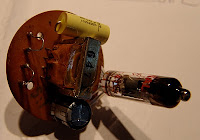
The magnetic field is provided by one large permanent barrel magnet. This microphone had a measured field of about 1200 Gauss between the poles, with ribbon dimensions of 5.5 mm wide by 67 mm long.

The original ribbon – sadly very oxidised – was of the piston type, with corrugations at each end and a flat section in the middle region. On closer inspection, the ribbon appears to have been designed for in-field replacement: each end is terminated in a thicker, silver-plated fold of foil, with a hole drilled for ‘easy’ mounting (easy being a relative term in this case). The ribbon is held in place with two brass clamps, each mounted held in place with a singe screw. The disadvantage of using a single screw rather than a pair for the ribbon clamps is that the clamp has a tendency to rotate as it is tightened, which can distort or wreck the ribbon. The clamps are soldered to wires which run to the transformer primary, and these wires are doubled (or tripled) in each case, presumably to keep resistance noise to a minimum.

With a rewire and a new (corrugated) ribbon the microphone works and sounds rather full and rich. However, the output transformer is wound for high impedance output, and won’t drive a standard mic preamp – so the microphone benefits from using an active buffer or an impedance matching transformer. Hum is also an issue with this, despite the massive brass housing.

I haven’t seen another one like this – either in life or on the web. If you have any further information on this, I’d love to hear from you.

Mic of the Month – RCA Junior ribbon mics

October was a bad month for blogging – I was busy with the haunted house sound installation, and this was compounded by a fault with my Macbook, which took the Apple repair centre three weeks to find and fix, a long time to track down a faulty cable. With a microphone, that would be the first thing to check! Amongst all the chaos I completely forgot to do the ‘mic of the month’ column.

Back in the real world, I have chosen the RCA Junior ribbon for November’s Mic of the Month. This is because they seem popular at the moment, and we’ve seen four at the workshop for service or repair. The fun thing about this family of microphones is that they vary somewhat in construction, so it is possible to compare and contrast versions from different eras. They tend to be a bit more affordable than the bigger RCA 44 and 77 mics, but still have a good tone that is very usable in a modern studio, especially if the ribbon is in good condition and the transformer is healthy and wired correctly.

The ‘Junior’ was created as a budget version of the RCA44, with a similar motor assembly but smaller magnets and housing. The most commonly seen models are the ‘black badge’ and ‘red badge’ versions, and these are actually quite different inside – the black badge model has a 3.0 mm x 55 mm ribbon, whilst the red badge version I examined has a wider, 4.5 mm ribbon and a stronger magnetic field.

The output transformers on these microphones can be set for 50 Ohm, 250 Ohm or 10KOhm output impedance, and it is worth checking that the mic is wired correctly to get the best performance with modern studio equipment. Normally that will be the 250 ohm setting.

The earliest and rarest version, the MI-4010-A, is shown on the right in the picture below. It is slightly larger than the later versions, with a different ribbon assembly which has horseshoe style magnets around the back of the ribbon. The magnetic field in this example is weaker, and the output lower than the more modern versions, although the tone with a new 1.8 micrometer ribbon is very pleasing. 

Finally, some RCA mics were actually made in Europe, and it would seem that some appear under different names. The microphone on the left is badged as ‘Magneti Marelli, Milano, Italy’ but is almost identical to the black badge RCA 74b. The only difference is that the Magneti has an alternative transformer, but still with high and low impedance options. The sound is every bit as good.

We’d love to hear from anyone who knows more about the Magneti Marelli microphones and their relationship with RCA.

(Thanks to Jules at DADA Studios in Belgium and Jørn Christensen at Rodeløkka Studio in Norway.)

Microphone of the month – Old Czech tube mic: Tesla?

This is the first ‘Microphone of the Month’ blog, featuring classic or unusual microphones. Hopefully I’ll manage to find time each month for this!

This old Czech tube microphone – a recent ebay find – may well have been made by Tesla. The capsule is connected using a connector that can also be found on old Tesla and Phillips microphones. Some of the capacitors are also made by Tesla, who were a large state owned electronics company in communist Czechoslovakia.
The ‘Tesla’ looks very much like an imitation of the Neumann / Gefell CMV563 bottle mic. In fact the microphone is smaller in diameter than the CMV, has no output transformer and has an unbalanced output. Like the CMV, the capsule may be swapped, and presumably other polar patterns were available. This one is marked with a red circle, which probably means omnidirectional. (I have yet to test the capsule).
The amplifier is a very simple grounded cathode amplifier, based around a Soviet 6Ж1Л (6Z1P) tube, which is a small signal pentode similar to EF95. These are also found in some Lomo and Oktava microphones, including the Lomo 19a9 and Oktava MKL2500.

Without the original power supply we can only speculate on the operating voltages. However, a B+ supply of 90V would be a good place for experiments to start – this would give a voltage on the capsule of around 60, and a sensible current through the tube circuit.

Unknown German Prototype Tube Microphone – ‘The Unbekannt”

Unknown German tube microphone

Here is a recent Ebay find. It’s an unbranded tube microphone, and judging from the components probably from the 1960s, in what was formerly West Germany. We’ve called it the ‘Unbekannt’, which is simply German for ‘unknown’. The amplifier circuit is a 3 stage unbalanced transformerless design, using EF40 pentode and an ECC81 twin triode. The final stage is a cathode follower.

The schematic is here.

As is so often the case, the microphone has been separated from the original power supply, so it is not possible to say what the exact operating voltages would have been. However, the voltage divider for the capsule polarisation may give us a clue – 2 Meg and 400K would be a simple way of using a 240V supply to put 40V on the capsule.

The metalwork is nicely done, and is comparable to Reissmann, Thiele and Teladi microphones of similar age. It seems too well constructed to be a DIY mic, but the oddball range of parts makes us think that it is some prototype from one of the microphone makers of the era.

The capsule is quite unusual, but sadly is missing a diaphragm at the moment. It uses springs and screws to adjust the tension and space to the back plate, so this can be adjusted after installation. We’ll try to get that up and running very soon so we can see what it sounds like!

Syncron AU7A microphones Part 2

Last time I wrote about a pair of Syncron AU7A microphones. The capsules were in good condition, but the batteries had leaked, causing corrosion and damage to the circuit. For one of these mics I decided to fit a tube circuit based on a 6205 subminiature tube (5840* would do just as well or better)**.

Tube modified Syncron microphone circuit, 6V regulated heater supply omitted.

The Syncron capsule operates happily between about 40V and 60V, and a simple voltage divider was used to supply the backplate with a suitable polarising voltage. As the capsule is cardioid only, the circuit can be made as simple as possible, and there is no need for a capacitor between the diaphragm and the tube grid.

With a little creative hacking I was able to reuse the circuit board to construct a valve circuit, which avoids damaging the microphone further. Although physically larger, the tube sits where the transistor was (I even used the same PCB pads as the FET), and there is room on the underside of the board for a couple of capacitors. An added bonus is that the original transformer is quite suitable for use in a tube circuit, and was rewired in 10:1 configuration. The rest of the circuit – 5 resistors and another cap – fit on the ‘wrong’ side of the board in the cavity below the capsule housing. Then it is a simple case of wiring the connector to the circuit and connecting the capsule, taking care not to damage the diaphragm.

One thing to look out for with this arrangement is that the amphenol cable plug & connector on the microphone are the reverse of the normal gender, which means that there can be 110V DC on the exposed pins. Consequently care must be taken to connect the microphone before the power supply is turned on, otherwise a short sharp shock can happen. Of course this isn’t really an acceptable acceptable solution from a safety point of view.
In practice the microphone works very nicely and is suitably quiet for recording vocals. We tracked some female vocals with it yesterday and it performed very well in that application.
Meanwhile, I have managed to track down some 22V batteries from Farnell, which should be suitable for the capsule polarisation, so I’ll attempt to restore the second mic to its original state. More on that soon.
** With hindsight the 5840 may be a better bet as there is an internal connection between the cathode and grid 3. This allows you to cut off two of the leads, which means using up one less precious pad on the circuit board inside – space is tight!
**Readers familiar with the ‘Royer’ tube circuit will recognise the topology, although a few of the component values are different.

Xaudia blog post on phantom power for these mics.

Neumann Gefell UM57 experiments

Lately I’ve had the opportunity to play around with several vintage Neumann Gefell tube microphones – a CMV563 (below with UM70 capsule) , a M582 and a pair of UM57s.

These all have broadly similar circuits, with a EC92 tube and transformer coupled feedback. The UM57 is configured for different polar patterns, whereas with the CMV563 and M582 you have to swap the capsule. There are other differences – the schematics are shown here.

One particularly common fault with examples of these microphones is that the original electrolytic output capacitor can dry out with age. This is by no means always the case, and the capacitor in the UM57 on the left above was in perfect condition after nearly 50 years!  The one on the right has been replaced with an orange modern metalised film capacitor.

So what is the effect of ageing of this capacitor? As the electrolyte dries out, the absolute value of the capacitance drops, which will affect the frequency response of the valve amplifier inside the microphone. To simulate this, a capacitance decade box was wired in place of the output capacitor (C3), and the chart below shows how the frequency response changes as the capacitance decreases in 0.2 uF steps.*

Part of the circuit is shown inset within the chart. Although intuitively we expect the smaller capacitor to give us less bottom end, the network of the capacitor, transformer primary winding and resistor acts as a resonant filter, producing a peak in the bass region just above a sharp drop off. The human ear can perceive this as more bass – although not necessarily in a good way: the microphone may seem muddy or lack clarity.

So, having a good quality capacitor here is vital, and the value of this can be used to tweak the bass response if desired. Of course this analysis is just for the tube circuit inside the mic and does not consider the effects of ageing on the capsule itself – that’s a story for another day.

SJT Feb 2010

* Measured using a swept-sine wave from 1Hz to 48KHz.