MOTM – Grampian GR1 and GR2

It is time again for microphone of the month, and for May we have these lovely Grampian ribbons.

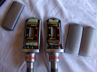
Grampian ribbon mics

Grampian mics come in a variety of model names and numbers which we will try to decypher. These were made in the 1960s and 70s by Grampian Reproducers Ltd, of Feltham in Middlesex, England.
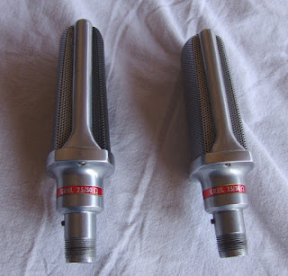
Grampian GR1/L and GR2/L ribbon mics

The mics are labeled GR (“Grampian Ribbon”), followed by a number and a letter. The GR1 designation was used for the semi-cardioid version, and the GR2 is the ‘normal’ figure-8 pattern. The letter shows the impedance of the mic, set by the output transformer winding. They come in Low, Medium, High, and ‘X’ flavours – the letter codes are as follows:

GR1/L and GR2/L   … 30 ohms
GR1/X and GR2/X  … 200 ohms
GR1/M and GR2/M … 600 ohms
GR1/H and GR2/H  … 50K ohms

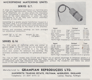
Here is a rather wobbly scan of the original Grampian data sheet.

The GR1 usually has a silver grill at the front, and a black one at the rear to show its asymmetry, whereas the GR2 has two silver grills. However, inside there is very little real difference between the two models, and any cardioidness* is imposed by additional foam padding around the rear of the ribbon. This foam usually depolymerises over the 40 years or so since manufacture, and the mics will typically fall apart when opened. If the mics have been stored for a long time they will require careful cleaning and new foam suspension before being put back into use.

The mics have a small thin ribbon, held in a removable plastic frame for ease of service. In that respect they are similar to the Reslos and Film Industries mics with which they undoubtedly competed. Unlike the Reslo and FI mics, the symmetrical magnet arrangement means that the GR2 has a true figure-8 response, and are suitable for Blumlein pair or a side mic in a mid-side array.

The internal transformers have a tendency to break, particularly on the H models which have very thin wires. If the break is in the right place the transformer can be repaired, but a rewind may be necessary.

Grampian plugs and connectors are a bit of a pain – they are getting scarce now, and rely on the barrel to make the ground connection, which can lead to hum if the connector is worn or oxidised. I have blogged previously about XLR conversions for these.
Grampian plugs

External matching transformers were also available, in case one needed to connect to an input of a different impedance. These are still handy for getting a bit more level out of the 30 ohm models.

These were mid-price microphones when they were made. I have a Grampian price list from June 1976, and the GR1 & 2 microphones were priced at £32.05 (plus tax) in a wooden instrument case, and £27.55 in a cardboard box. This would translate today as £180 to £334 plus tax, which would buy one of the better Chinese ribbons or a Beyer M260.

* I made this word up.

UFO over York

Strange cylinders were spotted today in the skies above the Xaudia workshop!

Actually it was the Good Year airship, but Aliens and Time Travellers are welcome to visit.

The kettle is always on, and there is a good pub round the corner.

Reslo RB 30 ohm & Hi Z mic wiring

Some Reslo RB mics have a transformer with a split secondary that gives the owner the choice of either a 30 ohm or high impedance output. Often these mics get dismantled and rewired, so here is where the internal transformer wires go….

For a 30 ohm output, yellow is the ‘hot’ output, and should eventually end up at XLR pin 2. White is cold, and goes to pin 3.

The green wire should not be grounded, but this sometimes happens by accident if the plug uses one of the pins for ground. The result is a high impedance path to ground from the output, which can act as a filter and give a weak output and weird frequency response.

Update May 2021
One reader reported that his microphone was reverse polarity after following this wiring diagram.
It is always a good idea to check polarity after any repair or modification. The polarity can be corrected by simply swapping over the two transformer output wires. 

Mystery mic motor

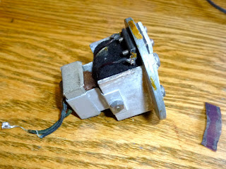
One of our readers sent in these photos of an unidentified ribbon mic motor. It looks like an attempt at a cardioid pattern, with the magnet and transformer located behind the ribbon. Presumably the original mic was a circular, end address arrangement.

If you recognise this or have any further information, we would love to hear from you.

Thanks to David for sending this in.

Reslo Black & Red Labels continued…

Last month I wrote a post discussing reslo microphones with red and black labels, and spent some time describing the transformers inside. Since that post I have measured more transformers, and the larger data set is beginning to show some definite trends.

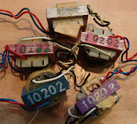
Transformers from Black label mics – type 10202 

Perhaps the most revealing transformer characteristic is the primary inductance. The DC resistance is also important in terms of noise, but seems pretty consistent across the measured transformers – usually around 50 mΩ for the primary and 1.2 ohms for the secondary. DC resistance should depend on the thickness of the wire and the number of turns used for the winding, and this seems to be common to the transformers although occasionally the leads may become oxidised.

Measuring the inductance is a little hazardous as it is dependent on the frequency at which the measurement is made. For most of the transformers I have measured at 1kHz and also 100 Hz, but the first few were just measured at 1kHz. The inductance at 100 Hz is usually around 3 times that measured at 1KHz.

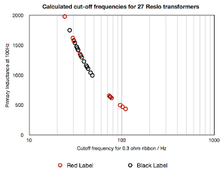
The graph shows the measured inductances at 1kHz and 100Hz when available (circles). The transformers marked with crosses were just measured at 1kHz, and the 100Hz value extrapolated from behaviour of the others.

Another way of looking at the transformer data is the relative cut-off frequency (fc) – the ribbon and transformer primary winding form a high pass filter. Assuming the ribbon has an impedance of about 0.3 ohms, then we can calculate fc. We use the value measured at 100Hz as this is closer to the frequencies of interest.

The transformers have a wide range of inductance / frequency values, but fall broadly into two classes. All but one of the transformers from the black label microphones show fc values of between 20 and 50Hz, whereas the red label ones have a much wider spread. About half of the reds are very similar to the blacks, but the others have a much higher fc value – between 70 and 110 Hz.

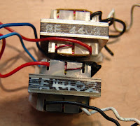
Many of the black label transformers are marked “10202”, and are occasionally painted in blue, pink or purple. These are sometimes found in red label mics too. The transformers with lower inductance have a ‘sandwich’ of laminations with darker ones in the centre, and these are often marked “SE 4402”.

SE 4402 type Reslo transformers

So it seems that we are somewhat closer to the truth about the red and black Reslos. The black ones are more consistent, and have a better chance of having a deeper bass response. Some of the red ones are just like the blacks, but about half the reds have a different, lower inductance transformer. These were probably designed for speech, and are not inherently better or worse than the others. However, if you are trying to record the lower frequencies of a bass instrument, or a fat electric guitar, then you may feel that the mics with the lower value for fare more suited to the task.

We have spare 10202 black label transformers in stock, and also make replacement full range 300 ohm transformers for Reslo RB mics. So if your Reslo doesn’t sound up to scratch, then get in touch!

Steampunk tube mic!

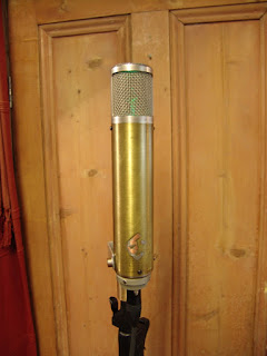
Here is a tube microphone that we put together for Jørn Christensen of Rodeløkka studio in Oslo, Norway. Jørn wanted a steampunk vibe… and that’s exactly what he got!

BBC R&D reports on ribbon mics

The good old BBC have made many of their research and development reports available through their website, spanning 1944 through 1996.

Below are links to some of the reports that relate to ribbon microphones. In many cases there is a lot of interesting technical data. The rest of the articles can be accessed here.

1945
The Crosley ribbon velocity microphone.

1947
Tannoy Ribbon Microphone

1953
Lustraphone VR53 ribbon microphone

The design of the PGD and PGS ribbon microphones.

The EMI microphone Type 2351E.

Tannoy microphone Type MD. 422.

1956
Design of the PGD and PGS Ribbon microphone Part 2

1958
RCA BK5

1961
Reslo RB

1965
Beyer M160

(Thanks to Santiago Ramos for sending the links.)

More bad magnets

These rather disturbing photographs are of bad magnets inside a T-Bone RB500 ribbon microphone.
Failed magnets in a T-Bone microphone

The coating around the magnets had peeled away, allowing the rare earth magnets to oxidise and expand. This process of course destroys the ribbon too. The magnets can be replaced, but may not be worth the expense.

I have seen a few microphones that look like this, and the worrying aspect is that it seems to happen spontaneously, possibly because the coating on the magnets was not of high quality, or perhaps they were scratched or cracked on installation.

Nearly all manufacturers now use neodynium magnets for their microphones, and I fear a epidemic in the future.

Many thanks to Andrea Cappellato for sharing the photos of his microphone.