Swapping the motor in Beyer ribbon microphone.

Beyer sell replacement motors which allow repair of some of their microphones although the cost in the uk is rather high. Swapping the motor is a bit fiddly but can be done with patience and care. This is more or less how I do it, although the models do vary a bit and you may need to improvise.

Beyer M160 motor with rounded edges (left).

First note that Beyer motors may have round or square edges at the rear of the magnets. For many microphones this won’t matter, but the M160 grill will only accept motors with rounded magnets. In the picture above it looks rather crude like it was rasped down with a file! It is probably possible to make a square edged motor fit an M160 but the magnetic filings would surely wreck the ribbon,

Also worth mentioning is that Beyer M160 and 130 have two ribbons whereas M260s have a single ribbon.

To exchange the motor, first one needs to remove the socket and unsolder the connector and transformer.  The socket may be glued, screwed and/or pinned in place. Remove the screws or pin. If the socket does not slide out then it is glued and will need heating until the glue fails. Do this at your own risk! 

Then unsolder the socket, remove any rubber grommets and unsolder and remove the transformer.

Beyer M260 with socket and transformer removed

The next job is to pull the motor through the acoustic labyrinth but keep in mind that you will need to reverse the process in a few minutes. I usually solder an extra piece of wire into the end of the motor leads which will let me pull the new motor wires back into place.
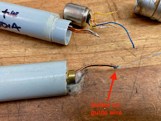
Remember to solder on a guide wire before you remove the motor

Once this is done you can pull the motor out and then unsolder, leaving the new wire in place.

Pull the motor and guide wire through the body

Unsolder the old motor and then reverse the process. Solder the new motor wires onto the guide wire, pull through the labyrinth and then unsolder. That parts is easier said than done because you are pulling some stiff wires around a bend that you can’t see. Reattach the transformer and socket. 

The only job left to do is to check the polarity of everything. Beyer do not always colour code their wires so you have to guess. Compare the microphone to a good modern mic. If your repaired Beyer is out of phase then simply reverse the wires at the XLR or din plug.

As a final warning, I have found that Beyerdynamic parts vary a lot and they do love to glue stuff together – why spend money on a screw or two when a tube of glue will do?  Be prepared for a certain amount of frustration and keep the swear-box to hand.

Bang and Olufsen BM5 grounding issue

Some Bang and Oulfsen BM5 stereo ribbon microphones are prone to hum on one channel. This is because the top half of the mic rotates around a plastic collet ring, but is only grounded through contact to the lower half of the metal body. With time and use, the contact between the two halves becomes loose, and the upper body is no longer grounded properly.

B&O BM5 stereo mic

The problem only occurs with early versions of the mic. Later, B&O recognised the problem and re-designed the mic’s rotating ring giving it an additional metal lip, so that the upper mic rotates around metal, ensuring good grounding contact at all times.

If you have a an early mic, in most cases the hum issue can remedied by improving contact between the parts as follows. Here are some tips, but remember that there is a delicate ribbon inside, so go slowly and if in doubt send it to someone more experienced!

1. Carefully remove the top half of the mic, and loosen the two grub screws at the base with a screwdriver of the correct size. Don’t lose these little screws – if you do then they are M2 thread!

2. Slide off the ring and put the rest of the mic somewhere safe.

3. Flip the ring over and rub over some fine abrasive paper to remove any dirt and oxidation.

4. Gently run the fine abrasive paper around the bottom of the metal tube that will make contact with the lower ring.

5. Replace the lower ring and tighten the screws, making sure that the metal parts are properly aligned and make good contact. You want a close fit between the tube and ring.

6. If that doesn’t work, addition of a strip of copper tape to the plastic collet can improve the electrical contact between the two parts. The tape will eventually wear out if the mic is constantly rotated, but many users tend to keep the same angle for most applications.

SJT, Feb 2014

Beebs to Belgium!

We have just shipped this rather lovely set of Reslo microphones to Thomas at Le Lupanar Studios in Belgium. He will be recording a brass section with two of our ‘Beeb’ Reslos, and a pair of upgraded cardioid Reslo CR mics on goosenecks.

His studio is still under construction but Thomas has been making a photo diary of the project – from the pictures so far it will be an amazing facility in a great location! How’s this for soundproofing…

Good luck with the building, and we will watch with interest as it all comes together.
🙂

G7 microphone

Jakob Erland’s Gyraf G7 DIY tube mic project has proved one of the most popular microphone projects. Several years ago I built a pair of these from scratch, and have since built several variations using different tubes, transformers etc. Below are a few notes on the project.

1. Using a single sided capsule

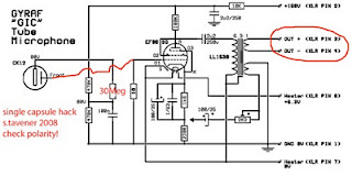
When using a single sided capsule, the circuit can be simplified somewhat and several parts omitted. The capsule may be wired straight to the tube grid, avoiding use of a coupling cap. Note that this affects the polarity of the mic, so reverse the output wires and be sure to check against an SM57 or similar know microphone. In this arrangement, the backplate polarisation resistor can be lower than 1 gig.

2. Some measured voltages:

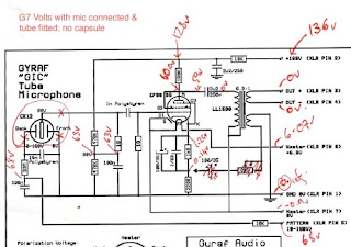
I built a version of the microphone by etching Gyraf’s layout. Wired it up and checked some voltages – and found that the supply is rather low under load. I got about 176 Volts without the mic connected, and was down to 136 V with the mic in the loop. Heater supply dropped from 6.3V (set whilst unloaded) to 6.08V. Here are some voltages for reference.

3. Better matching of the capsule polarisation voltages.

Note in the diagram above that one side of the capsule has a slightly higher voltage than the other – no problem in omni or cardioid but noticeable in figure8 mode when recording Blumlein pairs. Here’s a quick fix!