Syncron AU7a phantom power PCBs

Twelve years since first writing about the Syncron AU7a, I can finally offer a neat phantom power conversion. I converted a few of these in the past by hacking the original board or even building a tube circuit, but this is a better, tidier approach. A big thank you to Robert at Russell Technologies for designing boards and a better circuit from my sketches.

My Syncron AU7a converted for phantom power

The Syncron AU7a was one of the earliest transistorised condenser microphones, and was also sold as the Fairchild F-22. It ran on four mercury batteries, which had a tendency to leak after a few decades and are now obsolete. Conversion to run on phantom power seems sensible, but the original circuit used a P-channel JFET and positive ground, which are not compatible with modern phantom power supplies. A new circuit and a new PCB will make things a lot simpler. 

Syncron AU7a – circuit for P48 operation

We tried to stay close to the original philosophy, with a single transistor circuit which re-uses the Syncron transformer (above). The Syncron microphones that I have worked on did not use a source resistor bypass cap, but I had much better results with one in place. Dan Zellerman kindly supplied a version of the schematic which shows a 470 pF bypass cap, which was absent from my microphones. 

Working on these microphones is a bit of a pain because of the construction, and getting everything apart is the hardest part of this modification. The first job is to carefully remove the grill and capsule – put the capsule somewhere safe! The circuit is soldered inside a brass ring, and I needed to use a hot air gun and 80 watt iron to release that part. Some of the screws and mounting posts were also soldered in place. The transformer should be carefully removed, ready for re-use in the new circuit. 
New circuit board for Syncron AU7a

The board is then populated and soldered with the exception of R5, which needs to be adjusted to bias the JFET. Either a J201 or 2N3819 will work here. To find a suitable value for the source resistor, I connected a decade box and messed around until the junction with R1 was at 12 volts. (For this example, the value if R5 was 5K1 ohms.). Another way is to hook it up to a scope and inject a sine wave, checking for highest gain and lowest distortion of the waveform, or you can even do it by ear with a pair of headphones. You’ll get a similar value either way. Larger capacitors go on the reverse side of the board, along with the transformer.
Transformer side of the circuit board.

Some of the clearance is tight and care should be taken to avoid shorting to the ring that surrounds the circuit. And at some point that ring needs to be soldered to ground to ensure good shielding. I used an 80 watt iron on the outside of the ring and fed the solder in from inside. Any flux residue and other crud should be cleaned from the board when all the soldering is done. A drop of glue between the ring and board would also be sensible – be sure to keep the glue away from the high impedance components.

New AU7a circuit in place awaiting clean-up.

The capsule can now carefully be put back in position and connected to the circuit, followed by reassembly of the rest of the microphone. This updated Syncron AU7a sounds very nice and with the new circuit it has a useable output level and the signal to noise is good. The output impedance is approximately 200 ohms with the transformer secondary windings wired in series or 50 ohms if wired in parallel.

Inside the AU7a with the new circuit board.
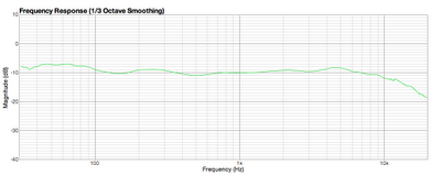
Below is a frequency sweep compared with a Sony C48 in cardioid mode. The updated Syncron has a similar output level to the Sony.
Syncron (green) and Sony C48 (blue) responses compared.

I can convert your microphone on request. Please get in touch.

Syncron AU7A schematic (again)

Many thanks to Dan Zellman, a former Syncron employee, who sent in this schematic for the AU7A condenser microphone. This was the ‘last issue’ diagram.

Syncron AU7A factory schematic
There are a few differences from my traced circuit that I posted in an earlier blog entry, most noticeably I had the 42V battery supply reversed.  Also, I have worked on several of these mics, but have never seen one with the 470pF capacitor present. 
SJT 25/10/14

Syncron AU7a revisited – Phantom power

A while back I wrote about the Syncron AU7a FET condenser microphones, which are sometimes badged as the Fairchild F22.

In that post I had sketched out the schematic. I have since converted one for a customer to run on phantom power, and spotted a glaring error in the schematic. Here is the revised version…

The transistor is of course a P-channel JFET, and the battery polarity is reversed, giving a positive ground. The batteries are switched off when the plug is disconnected, and the routing through the plug makes tracing a little tricky – that was my excuse anyway.

All of this means that some small modifications are needed for phantom power use, because negative ground is by far easier to implement. Using an N-channel JFET makes things much more straightforward – something like this…

The ‘adjust’ resistor is tweaked for best response to a sine wave applied across the head amplifier, and in this case the result was around 1kΩ. JFETs can vary quite a lot, and it is sensible to adjust this individually for each mic.

I built a small breakout board to supply the required voltages from the phantom power. The board fits neatly in the battery compartment.

The “110K” is again adjusted on the bench to ensure that the voltage is correct under load.

There is one more thing to note – now we have switched to negative-ground and an n-channel device, the output cap needs to be flipped round.

Here’s a measured frequency response plot for the modified mic (the dips at around 150 Hz and 600 Hz are likely to be room modes)…

The microphone works perfectly, and it is nice to hear one brought back to life after all these years!