Even in the simplest of tube microphone circuits, there are different approaches to connecting the microphone capsule to the tube. Let’s use a single-sided microphone capsule as our starting point.
The capsule behaves as a variable capacitor, changing its capacitance in response to changes in air pressure (i.e. sound). In order to generate a signal, the capsule needs to be polarised by some voltage, creating a difference in potential between the diaphragm and the back plate. This is the first decision that needs to be made – should the polarising voltage be applied to the diaphragm or the capsule backplate?
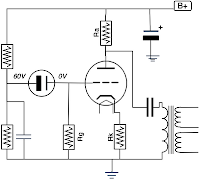
In the circuit shown on the left, the backplate of the microphone is polarised at 60V, which is obtained from the B+ supply, via a resistive divider and a small capacitor to stabilise and filter the polarising voltage. The membrane is connected directly to the tube grid, and a high value resistor (Rg, typically 100 kΩ to 1000 kΩ) connects both the grid and the membrane to ground. We have our potential difference across the membrane, and the sensitivity of the mic may be adjusted by increasing and decreasing the polarisation voltage. As the capacitance of the capsule changes in response to sound, a tiny current will flow through Rg, and this signal is amplified by the tube.
An example of this arrangement may be seen in the Neumann Gefell M582.
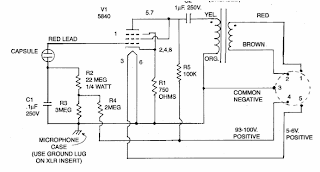
In some cases the grid resistor may be omitted. In the circuit below, which appeared in an article in Tape Op magazine by Dave Royer, the capsule diaphragm is grounded by grid leakage rather than a ‘real’ resistor. It works perfectly.
This simple arrangement is not possible when the capsule backplate is mechanically (and electrically) connected to the body of the microphone. In this case the diaphragm must be polarised directly.
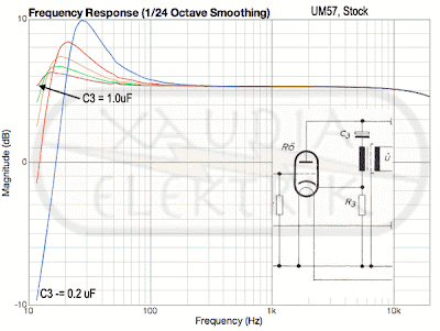
However, having a voltage of around 60V on the tube grid this would adversely change the operating points of the tube circuit, and so a capacitor must be used to block the DC voltage (left). Some listeners claim to hear the difference between different types of capacitors, and so normally a very high quality type should be used in this position. An additional high value polarising resistor is also required, otherwise the high impedance audio signal would be attenuated through the stabilisation cap.
An example of this method of connection is the Neumann-Gefell CMV563, which is designed to be used with bayonette style capsules such as the M7, M8 and M9.
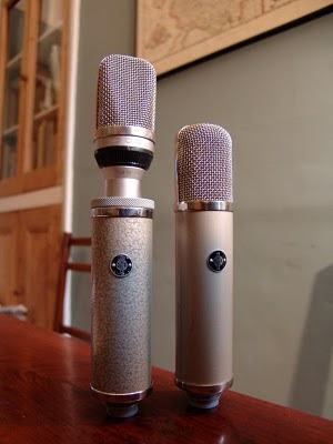
Sometimes it is the membrane which is connected directly to the body, such as in this Teladi K120. The approach is the same as the circuit above.


