|
| Reslo SR1 studio ribbon microphone |
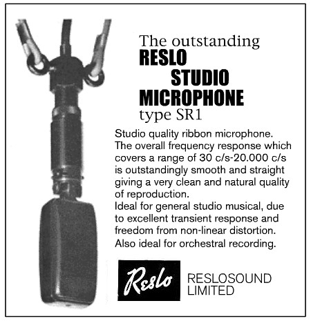
The advertising at the time claimed 30Hz to 20kHz – although doesn’t qualify that with a dB range.
 |
| Reslo SR1 (top) and RB microphones |
Extra sensitivity comes from using a longer ribbon and an extra magnet, and the mic is consequently about 1/3 as long again compared with the more common RB. By necessity the SR uses a different ribbon frame from other Reslo microphones. The mic below came complete with its original fibreglass stuffing – which protects the ribbon, damps any ringing of the shell, but seems to muffle the sound a little.
 |
| Inside the Reslo SR1 |
 |
| Reslo SR1 output connector |
The RB microphones are quite notorious for grounding problems, as the mic body is only grounded through mechanical contact at the plug. The SR1 deals with grounding in a better way. The output socket has a hole drilled in the centre with a small wire pushed down and soldered to one of the lugs (see photo, by the green wire). When the mic is reassembled, the long screw that secures the connector makes firm contact with both the mic body and the central wire, giving a good solid ground. This works well, and I now use this approach to ground troublesome Reslo RBs too.
 |
| Reslo SR1 transformer, being re-wound |
 |
| winding arrangement for SR1 transformer |
The SR1 was available in both 30/50 ohm and 250 ohm versions, and used the same laminations and bobbin as the later RB transformers, but with a more sophisticated winding configuration. The SR1 transformer has a 5-winding construction, with two primary windings alternating between three secondary windings.
We can supply reproduction SR1 transformers on request.
Thanks to David Pumple for sharing photos and information. The SR1 advert is from http://reslosound.blogspot.co.uk/.