This week we had a couple of nice reviews of the Extinct Audio family of ribbons microphones. I was involved in the design of these microphones and the start up of the business and it is nice to see them gaining some traction. This review was published on the German language site Amazona. You can read the original version here, which contains lots of useful sound clips and pictures. Below is an English translation.
TEST: EXTINCT AUDIO BM9 VIKING UND BLACK OPS, BÄNDCHENMIKROFONE
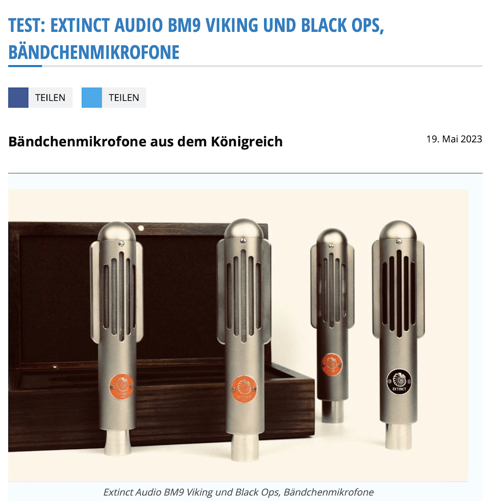
There are Englishmen that every child knows. Harry, Charles and William are currently the talk of the town, Ringo, Paul, George and John have written music history. Away from the limelight, there are four Brits, Stewart, Adam, Paul and Ant, who handcraft fine ribbon microphones in their small microphone forge Extinct Audio. Our author Raphael Tschernuth took a closer look at these fine British mics.
Ribbon mics have enjoyed unbroken popularity over the past two decades. While they were almost extinct until the early 1990s, they have been celebrating a resurgence at least since the Royer 121 and digital recording. The name Extinct Audio is an allusion to the fact that this type of microphone had almost disappeared from the face of the earth and was considered extinct. An old “Snake Stone” fossil, a local legend, serves as the company logo for the young English company.
Extinct Audio was founded by none other than Stewart Tavener of Xaudia.com, one of the reference addresses when it comes to ribbon microphone repair. In 2007 Stewart started to offer his service for ribbon microphones and since then the order book is bursting at the seams.
Some of you might be familiar with the microphone blog of Xaudia Elektrik, where you can find a lot of information about long gone microphone models of all kinds (links in the box below).
Since the founding of Xaudia, Stewart has had well over 10,000 ribbon microphones on his desk for repair. He knows them all – from great RCA classics to fancy designs from Italy or Denmark to modern China replicas. His experience over the last few years has finally led him to not only repair microphones, but to develop independent designs and bring ribbon microphones to the market himself.
Together with his friends Adam and Ant, he started Extinct Audio, with the goal of offering handmade ribbon microphones at a reasonable price. Stewart and Adam are musicians themselves and know how tough life can be with this profession. But not only did they want the mics to be affordable, they also wanted them to be responsibly made from local resources and meet the highest quality standards.
In fact, the company that builds the bodies is located just a few miles from the Extinct Audio workshop. The transformers required for a ribbon microphone are of their own manufacture. The wooden boxes of the microphones are made by a company that otherwise mainly produces wooden boxes for high-quality whiskey bottles. And yet the English somehow manage to keep the price in the €900 range, while other mics, such as the 121 from Royer or the Coles 4038, have seen huge price increases, especially in recent years.
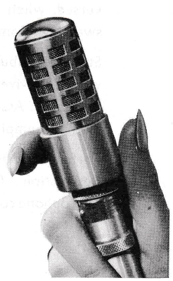
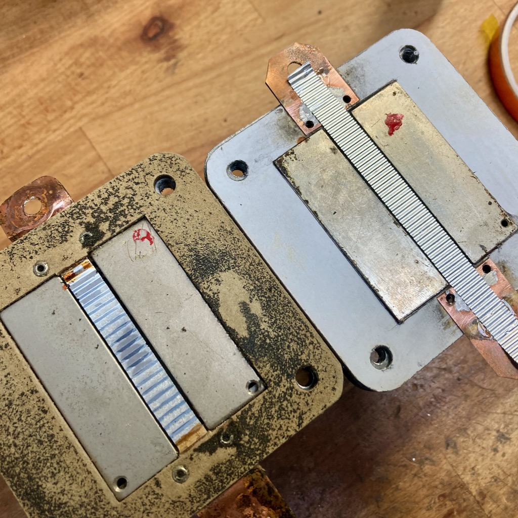
The underlying design of the two Extinct Audio microphones under review is based on the Bang & Olufsen BM3 which was developed in Denmark in the late 50s. This microphone was at the time one of the smallest ribbon microphones, its form factor was only made possible by the development of an ever stronger magnetic materials.
Perhaps some of you are familiar with the really thick ribbon microphones from the 1930s, such as the Siemens M25 or the BBC Marconi, each weighing in at over 4 kilos. The high weight and the high mass were necessary at that time, because there were no magnetic alloys with which strong magnetic fields could be realized in a space-saving way, as today with modern neodymium variants.
The BM3 from Bang & Olufsen was a revolution in the 1950s and was and was an inspiration for the Royer R121 in the 90s. The newly available neodymium magnet materials helped the Royer 121 achieve tremendous output. The Extinct Audio BM9 is also based on the concept of the BM3, even keeping the BM naming for “ribbon microphone.”
The BM9, nicknamed “Viking,” is a general-purpose ribbon microphone with a pure figure-of-eight characteristic. In terms of sound, it is clearly in the tradition of legendary ribbons such as the RCA 44 BX, Melodium 42b, etc. Its full-bodied bass range paired with brilliant highs gives voices and instruments an inimitable “Bigger Than Life Sound”. The proximity effect is, as typical for this type of microphone, very pronounced and therefore a little distance to the sound source is recommended.
No less than the great John Williams used various BM9s for the recording of his soundtrack to Star Wars for the orchestral recordings. And this for a production that can afford any microphone imaginable. This could almost be called an accolade for Extinct Audio (not to be overlooked from about 30 seconds on):
The Black Ops, on the other hand, is recommended for all applications where the microphone is to be positioned close to the sound source. It is particularly well protected against wind and air currents, and its specially adapted transformer ensures a well-balanced sound even at a very close distance from the sound source.
This allows the Black Ops to be positioned directly next to a guitar amp or snare drum, for example, without having to equalize the bass range by using an EQ. Like the BM9, the treble imaging is incredibly detailed and smooth for a ribbon microphone. The Black Ops was designed for harsh live use; among others, the English band Foals relied on various Black Ops for their recent live tours.
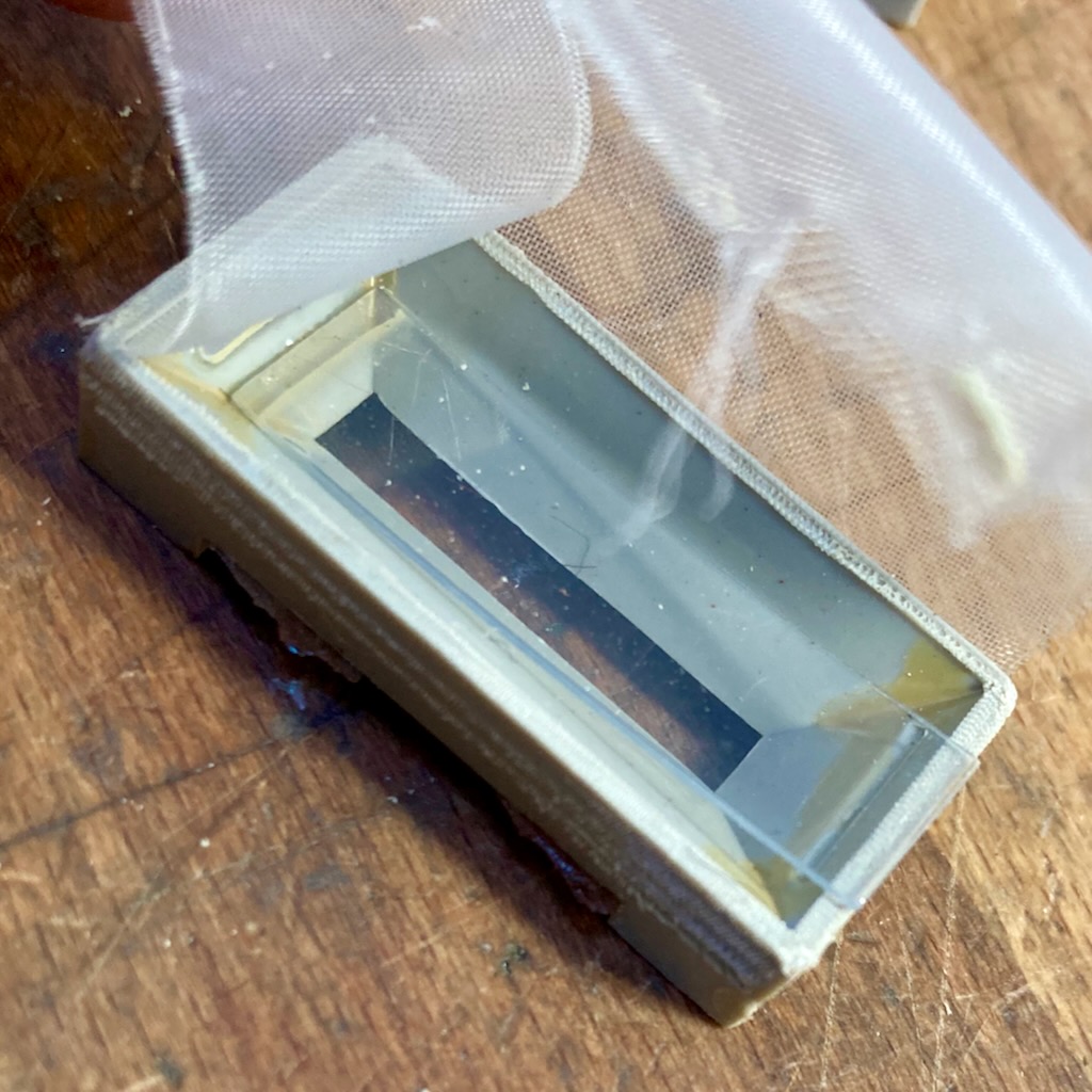
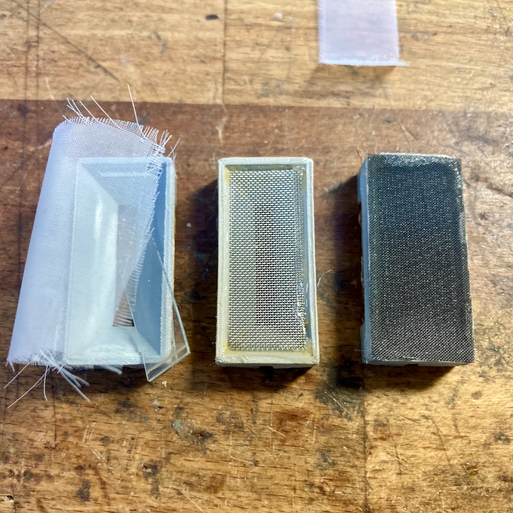
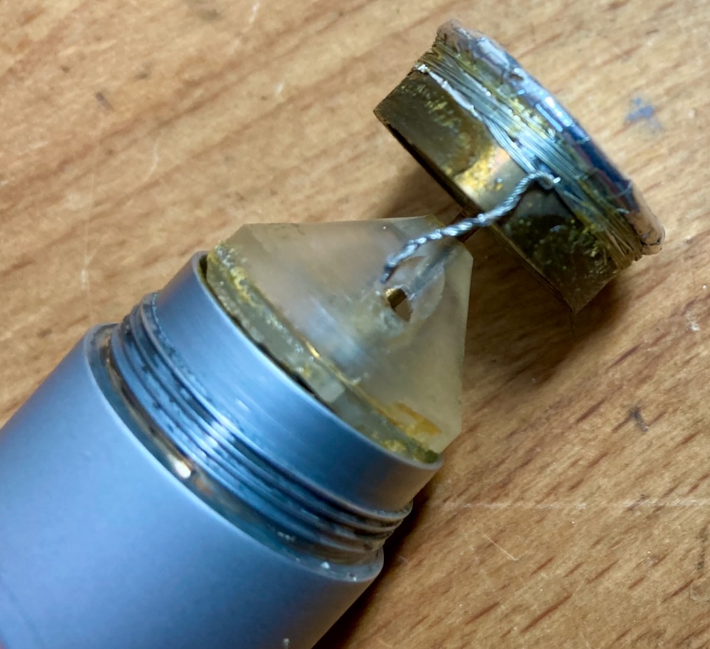
The “classic” BM9 Viking uses a 1.8 µ thick ribbon, the Black Ops uses a slightly thicker 2.5 µ. For comparison: the thread of a Spider’s web is about 6µ thick, a human hair even 50µ. Therefore, one should be as careful as possible with this type of microphone.
The frequency range of both mics is between 30 Hz – 15 kHz and sonically the foreground and rear are absolutely identical. While the BM9 has an impedance of 300 ohms, the Black Ops has an impedance of 250 ohms – in practice this is irrelevant, as both mics with these values will harmonize perfectly with current preamps. The sensitivity of the BM9 is 2.23 mV/Pa, a high value that does not demand too much from the microphone preamp. Thus, the BM9 delivers a higher signal than many a moving coil candidate. Nevertheless, it should be mentioned at this point that ribbon mics often benefit sonically from stand-alone, external preamps. For entry-level or mid-range audio interfaces, an inline amplifier is a good choice, and the market is now teeming with them. Alternatively, one can also fall back on an active variant.
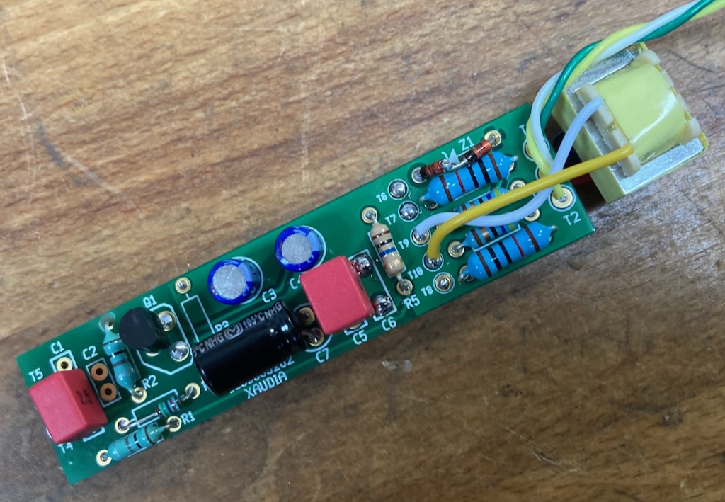
While testing the two mics described above, the manufacturer posted on Instagram that development of the active variant was complete. Without further ado, I made an effort to get hold of one of the first series models for the test and I was sent the first available stereo set. The active circuit increases the output signal by about 22 dB of noise-free gain. This significantly relieves the preamp and the recorded signal is comparable to that of condenser microphones. We will also consider this model in the practical test.
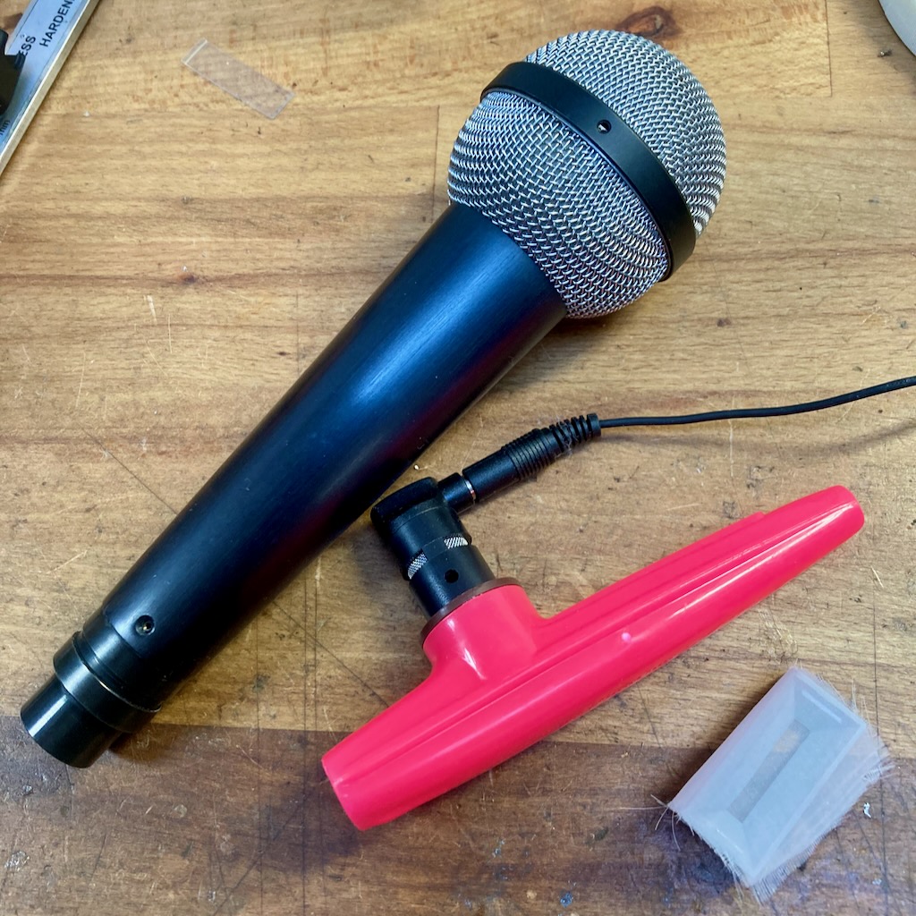
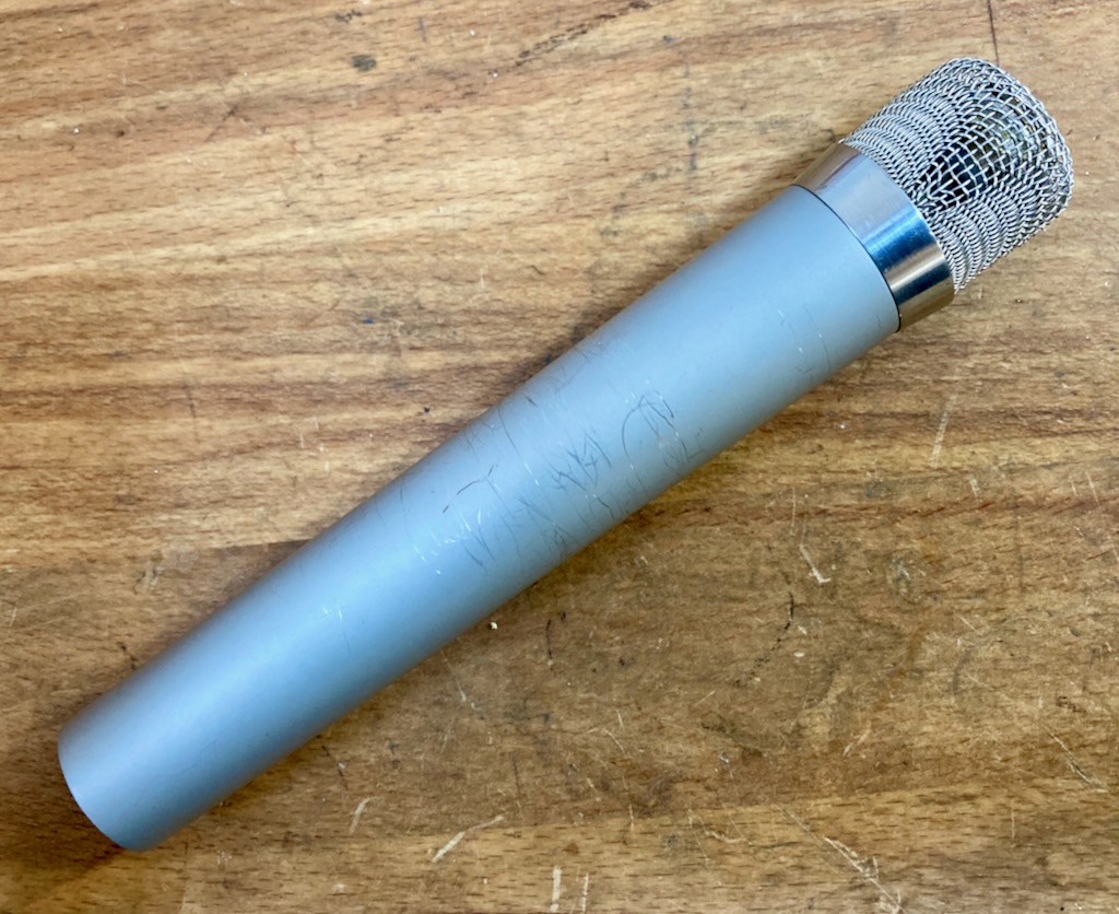
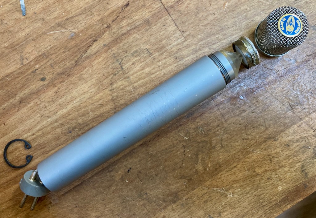
Extinct Audio offers manufacturing character par excellence with its microphones. When unpacking the microphones, the testers can’t help but be amazed at how much love and attention to detail has gone into the work.
The wooden cases are, as already mentioned, not cheap barware from the Far East, but extremely solid and excellently crafted. They offer perfect protection for one or two microphones. A serial number is emblazoned on a metal plaque on the outside, and inside the casket a signed certificate provides information about the day on which the microphone was manufactured and which employee took care of which production steps. The microphones themselves are beyond reproach in terms of workmanship.
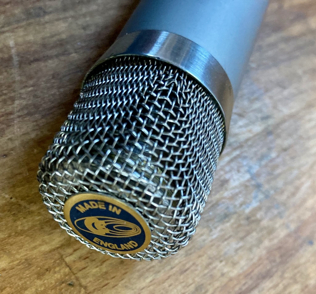
This is pure perfection, without compromise. Metal workmanship and are excellent, logo and metal gauze perfectly attached, all edges rounded, the serial number engraved on the back – that’s how it should be. With their 355 grams, the Black Ops and BM9 feel good in the hand and radiate their very high value. Due to their light weight, they can be securely positioned even with simple microphone stands and are easy to set up. A screw-in mount was also included with the review sample, but ordinary medium-sized microphone clamps can also be used.
If there is one application that one immediately associates with the Royer 121, it is the miking of a guitar amp. This ribbon mic has earned legendary status since its introduction in the late nineties. Compared to many classic ribbon mics, it delivers a somewhat thinned-out bass image and can be positioned relatively close to the amp. With an old, venerable Coles 4038, for example, the immense proximity effect would absolutely require the use of a high-pass filter. So with ribbon mics, it’s always a matter of finding the sweet spot and using it profitably in your work.
In the following audio sample, you can first hear the mentioned Coles 4038 at a distance of only 13 centimeters. The recording is much too bass-heavy due to the proximity effect. After applying a high pass filter (100 Hz, 24 dB/oct) the tide turns and the sound suddenly becomes usable, possessing a “creaminess” typical of ribbons:
In comparison, you can hear the sound of the Shure SM57 dynamic moving coil microphone, which is considered the “industry standard” for amp recording. This is much more “grainy” and garish to work.
In terms of sound, the Extinct Audio BM9 Viking ribbon microphone is on the “classic” side of power. Similar to the Coles 4038, it therefore requires the use of a high-pass filter to deliver a balanced signal at a distance of only 13 centimeters:
The Extinct Audio Black Ops, on the other hand, does not require an additional filter, since the bass increase was compensated for by the transformer used. As a reference, you will also hear the Royer 121 afterwards, unprocessed at a distance of 13 centimeters from the speaker. Again, an HP filter would suit the signal well. With Black Ops, on the other hand, the signal is immediately “mix-ready”.
The different proximity has a direct impact on the use. Positioning all microphones at the same distance in front of a sound source would therefore be extremely bad for a meaningful test report, since every microphone deals differently with the bass boost and has its own sweet spot. The BM9 is full-bodied, with the Royer 121 the proximity effect is somewhat reduced and with the Black Ops it is somewhat less than with the Royer. On the acoustic guitar I therefore decide on three different distances
Extinct Audio Black Ops: Distance 30 centimetres
Royer 121: distance 40 centimetres
Extinct Audio BM9 Viking: distance 50 centimeters
Many thanks at this point to the really impressive singer/songwriter Fabian Holland, who recorded the acoustic guitar for this test.
The test shows that the Extinct microphones can easily compete with the Royer 121 in terms of sound quality. This is impressive when you consider the price difference of almost 1000 €. Ribbon microphones are also excellent for imaging percussive instruments. One reason for this lies in the natural mapping of the transients, which are mapped very quickly and vividly.
In the following example you hear the drummer Achim Färber. The BM9 stands a few meters away from the drums. It is a mono recording without any effects. The Black Ops was positioned on the snare, also without any change in signal:
During the test period, the Black Ops has become one of my favorite microphones for the snare drum. The figure-8 characteristic makes it excellent for masking out adjacent toms or hi-hats. The strong attenuation on the 90- or 180-degree axis can be used excellently.
Last but not least, here’s a short sample I recorded myself with two BM9s as overheads and a subkick. As before: no EQ, no compressor… nüschte, as the Berliner says.
During the test period, I had the chance to use the Extinct Audio Mics on many other sound sources. They delivered excellent results on cello, as a stereo Blumlein set on piano, or on vocals with soft S sounds. The stereo pair was also perfectly matched before delivery, and the two measurement curves were absolutely identical.
By the way, the active version sounds exactly like a passive BM9, only louder. Sure, you could also loop in an inline preamp like the Fethead, but that makes the construction a bit unwieldy on the one hand, and on the other hand the shielding falls by the wayside. Unfortunately, inline preamps are prone to turning cell phone radiation into audible tones. When the network builds up, beeping and whistling can therefore be picked up unintentionally. The active version is well shielded in this respect and does not transfer any noise to the audio signal. And by the way, it looks much better…
Final Thoughts
Chapeau! The small microphone workshop Extinct Audio, delivers with the BM9 Viking and the Black Ops two ribbon microphones that leave nothing to be desired. The workmanship was done by hand with great attention to detail, the materials used are high quality, locally “sourced” and guarantee a long life. Each microphone is individually measured before delivery and stereo pairs as well as active +48 variants are also available. The latter brings the already high output to the level of a condenser microphone. Sonically, the BM9 is in the tradition of legendary ribbon microphones, while the Black Ops is predestined for close miking. Both reproduce percussive instruments with tangy transients, deliver vocals with smooth S-sounds, and are predestined for a wide range of applications and sound sources. In addition, they possess a remarkable top end for microphones of this type. Combined with a very good price/performance ratio, this leaves an unclouded picture that clearly stands out from many Asian competitors due to the high quality.
+
Excellent workmanship
Very good stereo matching, measured values
High output
Very versatile
Great, classic ribbon sound (BM9)
Balanced sound when positioned close to the sound source (Black Ops)
Durable design, handcrafted, made from local resources