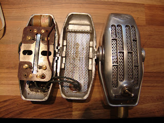
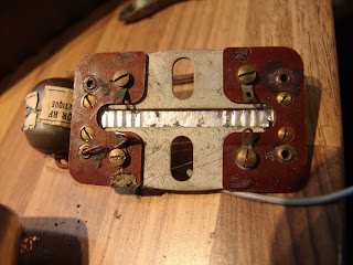
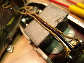
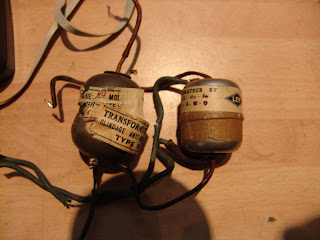
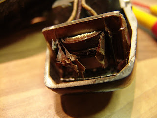
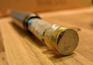
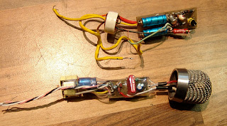
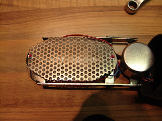
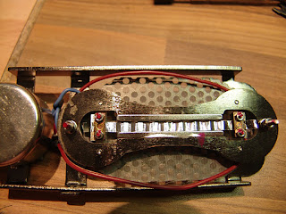
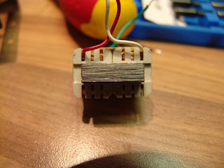
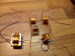
I found this ribbon / magnet / motor assembly inside a Reslo RBL microphone…
..which is very different from the usual Reslo motor design.
I have never seen this type, and I don’t know if it is an attempt by Reslo to upgrade or modernise the old design, a transplant from another make of microphone, or a good quality DIY repair job. It remains a mystery!
This is the inside of a client’s Avantone dual ribbon microphone, which was in pretty bad shape.
The metal plating on the neodynium magnets has suffered a catastrophic failure, and in doing so has been pushed out, crunching the ribbons and covering the whole assembly with powdered neodynium alloy. Not good.
The cause of the failure is still a mystery – perhaps it could be due to a process failure in a batch of magnets, or maybe the mic was exposed to an excessively humid environment.
I have seen other mics with signs of flaking on the magnets, but nothing this serious. Neodynes are still a relatively new magnet technology, and how they will stand up to years of studio use and abuse remains to be seen.
Happily, we were able to bring the mic back to life by replacing the magnets and of course re-ribboning the mic.
Ronnie at Diesel Studios in Italy sent in a pair of T-bone RB500 ribbon mics for service and upgrade. Ronnie asked for some photos of the process, and I thought they would make a nice photo-blog.
Here is one of the mics on arrival…
Inside the body, there is further screening to protect the ribbon, and the transformer sits in a metal can.
One of the old ribbons.
This one is not so great!
New 1.8 micrometer ribbons….
The old transformer has primary DC resistance of 90 milliohms, and 30 ohms for the secondary. Those laminations are not very well packed.
Winding new transformers for the mics.
Potting the transformers in the wax bath keeps the coils and laminations from vibrating….
The finished transformers. We may as well re-use the metal can for some extra screening.
The Sony C38b is held by a yoke, and the stand mount contains a pair of rubber diaphragms which provide a little bit of shock absorption for the mic.
With time the rubber ion this one has perished, leaving the mic to flop around, rattle, and – worst of all – fall off the mic stand.
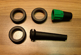
Here is how i fixed one with a strain relief rubber grommet, three rubber rings, and a jack plug bushing. The rubber rings are 23mm OD, 16 mm ID, and are the kind available (at least here in the UK) for fitting metal boxes for a ring mains, to stop the cables rubbing. The grommet measured 14 mm OD, 5 mm ID, with a recessed ridge diameter of 9 mm, and is cut off at the bottom to fit.
Firstly, unscrew the large grey knurled nut and take the mount apart. All the old rubber needs to be cut away. Then push the new strain relief grommet into the centre hole in the large grey knurled nut. Remove the bottom nut from the centre screw that is attached to the yoke, and push this into the centre of the grommet. It should look like this….
Then, pack the barrel of the mount with three rubber o-rings.
I then used a bushing from a Neutrik jack plug and inserted this into the centre.
Finally, push the re-rubbered yoke into the centre, and firmly hand-tighten the knurled nut. It should look like this.
The new assembly doesn’t give as much ‘bounce’ as the original, but it holds well, doesn’t rattle, and most importantly, it doesn’t fall off!
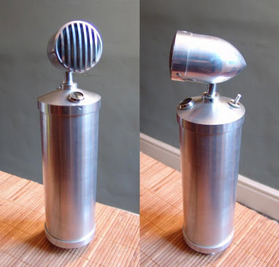
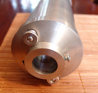
Big old German bottle microphone (flaschenmikrofon)
This time-capsule condition, stunning bottle mic is a recent ebay find, but we know very little about it! So, if you recognise this one, or have any further information, please get in touch.
In looks, this is very much in the style of an RFT CM7049 or a Neumann CMV3, but doesn’t match any of the models that I am aware of by those manufacturers. The mic stands around 320 mm tall by 80 mm diameter, and is beautifully machined from aluminium, so we’ll call him ‘Big Al’.
The bottom bell is secured by two thumbnuts, which make access to the tube and battery compartment very easy.
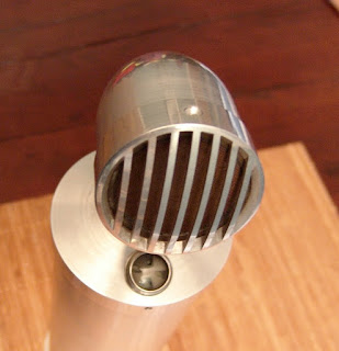
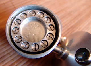
The capsule is held in place by a clamping ring with 12 screws, and the diaphragm looks to be either nickel, or some kind of metallised film. It is not possible to get the capsule out of the head without removing these screws – not something I really want to be doing. It is even possible to work out the backplate hole pattern from the dents in the diaphragm.
Bottle microphone capsule
The tube is a Telefunken DAF11 which dates back to the 1940s. I haven’t met one of these before, but the datasheet is available at Frank’s, and shows it to be a diode and pentode in the same shell, with a common heater & cathode.
DAF11 tube
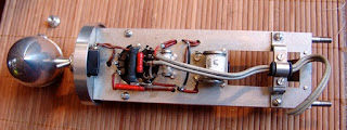
The diode part is not used in this mic. The heater supply is a modest 1.2V at 50 mA, and is designed to run from a battery cell.
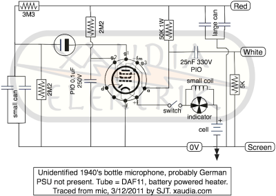
DAF11 bottle mic schematic
I traced out the circuit – the heater supply does indeed come from a battery, and there is a space inside the mic for a large cell. The switch on the top of the mic breaks the filament supply, saving battery power and (eventually) muting the mic, and there is a Neumann / RFT style indicator. in the top.
The capacitors in the rectangular metal cans are not labelled, but each can contains a pair of caps with a common negative terminal. On the bench, all four caps measure 1.0 ± 0.2 uF, and the different can sizes must reflect different voltage ratings.
There is no grid resistor present in the mic – either it has been removed for some reason, or the design relies on grid leak to set the bias.
Update 7/12/2011
We had a nice little discussion about this mic over at GroupDIY.
This Stellar RM3 ribbon microphone recently came into the Xaudia workshop for a transformer upgrade and new ribbon, which of course gives us a chance to poke around inside and take some photos.
Stellar RM3 with new Xaudia transformer and ribbon. The old transformer in in the foreground
The design closely follows the Speiden / B&O / Royer style of microphones – possibly a little too closely for comfort! Like the B&O mics, the ribbon frame slides out of the top, along with the transformer and lots of synthetic woolly packing. The body forms part of the magnetic return circuit, so it was good to see that this one was made of a magnetic steel, rather than brass or aluminium. In my opinion this is one of the better made of the budget ribbon mics.
As is commonly the case with budget microphones, the design is let down a little by the transformer, which measured 47 mΩ (milliohms) on the primary winding, and 90 Ω for the secondary, with a turns ratio of 1:54. Overall the mic gave a measured output impedance of about 650 Ω, of which over 200 ohms is pure DC resistance from the transformer. And in ribbon mics, resistance equals noise.
The new Xaudia 595/40 transformer (in this case a 1:40 ratio) has DC resistances of 0.02 Ω for the primary and 16 ohms for the secondary – much lower than the stock trannie. Although the lower transformer ratio would be expected drop the output level of -2.6 dB, the thinner, lighter ribbon gives an almost equal but opposite effect, and the output levels before and after are very similar. However, the lower DC resistance of the replacement transformer gives much lower noise, and the larger core allows higher sound pressure levels before the onset of saturation.
November’s microphone of the month is a British long-format ribbon that was sold under the names “Lustraphone” and ‘Grundig”.
A Lustraphone-badged ribbon microphone in glorious brushed stainless steel finish
This mic was available in at least three different impedances, and I have come across 30, 200, and high impedance models. Unfortunately the badge often falls off so you don’t always know what you are getting! Most of the models I have seen are finished in a bronze hammerite colour, although there is a deluxe low impedance model which has a gorgeous brushed stainless steel finish. Despite the different badges and finishes, the mics are exactly the same on the inside (transformer aside).
Lustraphone ribbon microphones on the bench
One of the ribbon clamps sits on a spring-tensioned screw thread, which allows fine adjustment of the ribbon tension. This makes tuning the ribbon very straight-forward, and allows the owner a little bit of grace if the ribbon becomes a little stretched over time. This feature should probably be mandatory on all ribbonmics!
Grundig badged lustraphone mic, opened up for service
The magnetic field is supplied by a pair of horseshoe magnets (which unfortunately sometimes age with time, losing their strength). Connection to the rest of the world is made by a balanced three-pin paxolin plug, which are hard to come by now. The middle pin is ground, with the audio on the outer two pins.
Rear connector and original plug.
Fortunately, a male XLR connector can be modified to fit by slicing off part of the barrel.
XLR connector modified to fit the mic.
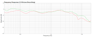
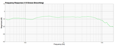
The long ribbon and motor design gives these mics a full bottom end and a pronounced proximity effect. Here are the frequency plots for three of these mics that we have serviced recently:
Lustraphone ribbon mic frequency plots.
(Thanks to Mark Stevens for additional information).
Update 23/1/12. These microphones were also sold under the brand Pamphonic. One appeared recently on ebay:
Update 29/2/12. And here is one with a Mimco badge!
Sometimes I see patterns or trends in what arrives on the bench. A year ago it was RCA 74s, and in spring 2011 it was Electrovoice ribbon mics. And then the summer brought Melodium 42bs. Of course these are just statistical anomalies or ‘blips’ in the random noise of what my customers send me to repair, but it does at least suggest ideas for the regular ‘Microphone of the Month’ column.
Cadenza microphone set with box, documents and stand
This month these little Cadenza ribbon microphones are in vogue – these were made by Simon SoundService Ltd in London, and were designed by Eric Tomson, Stanley Kelly Peter Bell. The mics have a very 1950s styling, and are often called ‘rocket’ mics. However, having spoken to a couple of customers, the consensus was that many of these microphones no longer sound as good as they should – or at least as good as they look. The complaints are that they are noisy, with low output.
The Cadenzas have dual impedance outputs, and can be wired for either 30 ohm or high impedance (80 KΩ) output by changing the wiring at the connector. Neither option is really ideal for modern studio use, where something between 200 and 600 ohms is much more common for a mic output.
The ribbon itself is slightly unusual in that it has a fixed or nodal point half way along, where the ribbon is glued to an insulated support. This may well have been designed to reduce the likelihood of the ribbon being stretched, and one can imagine this either as two ribbons in series, or like a guitar string where the octave harmonic has been struck.
Cadenza mic transformer under the knife
From a technician’s viewpoint (i.e., my opinion :p), there are a some weak points in the design which all relate to the transformer. Firstly, the ribbon clamps are connected to the transformer simply by winding the wire under a nut and tightening it – really not a reliable long term approach. Secondly, the transformer wires are extremely thin, and half a century later the insulation becomes brittle and tends to break, with disastrous results. It is more common practice to use thick gauge wire for the fly-leads to the primary, to keep resistance and noise to a minimum. And finally, as these thin wires become old and oxidised, the mics become noisy.
This all points to a transformer upgrade or rewind. However, it seems that Simon Sound Services Ltd. did a better job of encapsulating the transformer than they did of connecting it to the ribbon. The tranny is glued inside a mu-metal can with a hard, clear resin that resists removal. It was necessary cut the metal shell in half and then to soak the resin in dichloromethane for 48 hours to remove the resin. This allows removal of the laminations and a better inspection of the transformer windings.
Cadenza windings – primary (left),
and 30 ohm output (right)
The outer high impedance winding is a very fine gauge (approx. 0.07 mm), below which is a single layer of 0.4 mm wire which makes up the primary. The innermost winding is the 30 ohm output, which is approximately 0.2 mm in diameter. Unfortunately the solvent also damaged the bobbin, and and a replacement was found to make a new transformer using the vintage laminations.
The new transformer has a single 600 ohm output, with thicker gauge wires to give lower resistance. It took some effort but the result is a higher output with a lower noise floor, and the mic is much more usable. I’ll post back with a ‘before’ and ‘after’ frequency plot for comparison.
This little dinosaur sculpture was made out of waste winding coils, stripped mostly from old Reslo and other microphone transformers. 🙂
So why are we stripping transformer coils?
Some older ribbon mics were originally wound for 30 or 50 ohm output impedance, and tend to give a low output level when connected to modern recording equipment.
Many of these low impedance mics, including Reslo and Tannoy ribbons, can be rewound for a modern 200 or 600 ohm input, raising the output to a more useable level, and avoiding noise from having to crank up the preamps.
Bobbin from Reslo transformer with secondary winding removed.
The old Relso 30/50 ohm transformers have an inner (primary) winding consisting of just 12 or 13 turns of thick (0.8 mm) enamelled wire, and a secondary winding of 152 turns of 0.4 mm wire. The thick wire of the inner winding ensures that the primary resistance is low, which keeps noise to a minimum.
Reslo transformer rewound for 600 ohm output
Re-winding the transformer involves removing the outer winding from the original transformer and replacing it with sufficient turns of a thinner gauge to reach the desired turns ratio and output impedance. Usually the original primary winding can be kept in place. The transformer is then reassembled and dipped in wax to fix the windings and lams in place.
This makes the microphone much more usable in a modern studio – transformers can be would for 250Ω, 600Ω or any other desired output impedance.