Here’s a fairly low-tech solution to a problem.

The Sony C38b is held by a yoke, and the stand mount contains a pair of rubber diaphragms which provide a little bit of shock absorption for the mic.
With time the rubber ion this one has perished, leaving the mic to flop around, rattle, and – worst of all – fall off the mic stand.
Here is how i fixed one with a strain relief rubber grommet, three rubber rings, and a jack plug bushing. The rubber rings are 23mm OD, 16 mm ID, and are the kind available (at least here in the UK) for fitting metal boxes for a ring mains, to stop the cables rubbing. The grommet measured 14 mm OD, 5 mm ID, with a recessed ridge diameter of 9 mm, and is cut off at the bottom to fit.

Firstly, unscrew the large grey knurled nut and take the mount apart. All the old rubber needs to be cut away. Then push the new strain relief grommet into the centre hole in the large grey knurled nut. Remove the bottom nut from the centre screw that is attached to the yoke, and push this into the centre of the grommet. It should look like this….

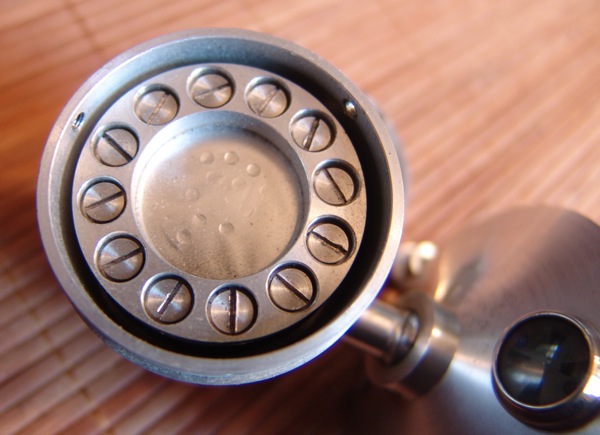
Then, pack the barrel of the mount with three rubber o-rings.

I then used a bushing from a Neutrik jack plug and inserted this into the centre.

Finally, push the re-rubbered yoke into the centre, and firmly hand-tighten the knurled nut. It should look like this.

The new assembly doesn’t give as much ‘bounce’ as the original, but it holds well, doesn’t rattle, and most importantly, it doesn’t fall off!
SJT