The Xaudia Blog

Geloso M88 dynamic microphone

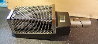
Here is a pair of funny little Geloso dynamic microphones, one is in pieces already.

Geloso M88 dynamic mics

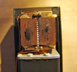
The build quality is nice – better than the early Geloso mics which tend to crumble. It has an internal two-bobbin humbucking transformer, to give an output impedance of 250 ohms.

Internal transformer for impedance matching duties

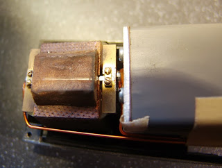
The diaphragm is made from a light plastic for fast response, and they sound nice, if a little light on  bass.

Geloso M88 diaphragm in good shape
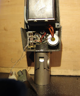
They use an annoyingly unobtainable 4 pin connector – I feel an XLR mod coming on…
The original unobtanium connector can be converted to XLR

🙂

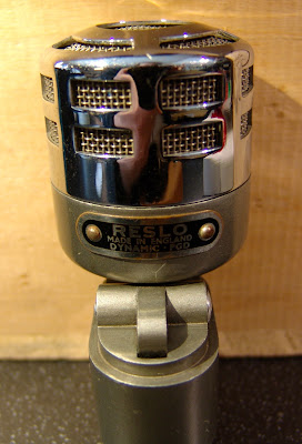
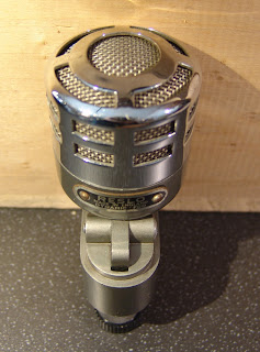
Short, stubby and dynamic – The Reslo PGD

Reslos are best known for their ribbon mics, but they made some dynamics too. 

Short, stubby and dynamic – The Reslo PGD
This early model is labeled ‘Dynamic – PGD’, which one assumes stands for Pressure Gradient Dynamic. It proudly says ‘Reslo’, on the badge –  the later RB mics were mostly labeled ‘Reslosound Ltd’.

The PGD appears to be made of leftover parts from the RV ribbon mics. The base of the mic is the same, complete with swivel mechanism, and the grill looks like a cut down version of the RB too. As usual it uses the annoying Reslo plug.

The head on the RGB could be tilted for best pickup of sound.
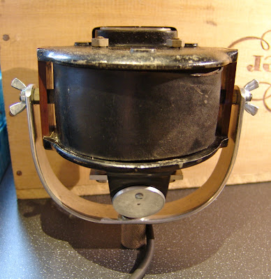
There is space in the base of the mic for an output transformer, although this 30 ohm example doesn’t need one. I don’t yet know if they were produced with other output impedances, but it would not be surprising, as later models like this pencil mic came with switchable outputs.
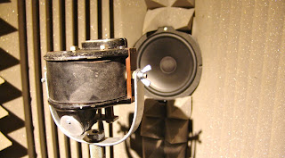
Reslo PGD – aluminium diaphragm

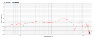
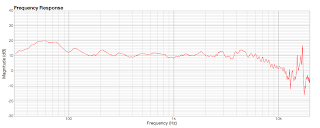
Like many early dynamics, it has a pressed aluminium diaphragm, which is heavy and stiff compared to later polymer film designs. Consequently has a quite lumpy response. Here is a frequency plot for one mic – other examples may differ!

Frequency sweep for Reslo PGD mic.
Thanks to Sean Davenport.

Experiments with Carbon Microphones

Carbon microphones were one of the earliest audio transducers, and were used for radio broadcasts up until the mid 1930s, when they were superseded by ribbon microphones. 


They were really simple devices, with small particles of carbon packed into a space between two electrodes and pressed against a plastic, mica, rubber, or wax paper diaphragm. When connected to a battery supply, a current flows through the mic which is modulated as the sound impinging on the diaphragm compresses and releases the carbon particles. 

Old carbon microphone – unknown manufacturer
I have been meaning to investigate carbon mics for some time, so when a couple came up for sale for £10 each, it seemed like the perfect opportunity to get my hands dirty. Literally. In German these are called Kohlemikrofon, which also translates as ‘coal microphone’. 🙂
Carbon microphone with the diaphragm and carbon removed.

The body of the mic is made of an insulating material, in this case a block of marble. The classic Marconi-Reisz microphone also used marble – this one is clearly a copy of that mic. Others had bodies made of wood, which must have been cheaper to make. Four hooks screwed into the body would have been used to suspend the mic within a metal ring, using springs or rubber rings, like this nice example at the ORBEM website.

Old diaphragm and grill from a carbon mic

After many decades this example is in pretty poor shape: most of the carbon has escaped into the wild, and the diaphragm is cracked and perforated. I wanted to try and get this working again, for fun and as a learning experience.

Clean again!

 The first step was to clean everything up in the ultrasonic bath, and the brass terminals were given a scrub. At least it looks better! The carbon will sit in the depression between the two brass terminals.

New diaphragm !

I made a new diaphragm by stretching a sheet of thick cellophane over the bakelite frame that makes up the front of the mic, and then heated it gently with a hot air gun. The plastic film shrinks and pulls itself tight. It looks neat and has a similar thickness to the original – as far as I can tell.

It took me a little while to work out the purpose of this big screw in the base of the mic. It is in fact for filling the microphone.

Then the mic can be re-assembled and filled with new carbon granules. It takes a few goes to pack the carbon, shaking the mic in between each fill.

Carbon microphone circuit, from the TFPro website.


I tried a circuit inspired by the one above, using a battery and transformer.  Ideally the transformer should be gapped, or a capacitor used to block the DC, to prevent saturation.

With a new diaphragm and new carbon, the microphone does now pick up sound, and although it is far to noisy for any serious recording, I was pleased just to get that far in my first attempt. As always with microphones, the art is in the detail and I can now at least appreciate some of the design parameters than need to be considered. These include

  1. Diaphragm material, tension, thickness and stiffness. The diaphragm needs to be thin and compliant enough to vibrate, yet stiff enough to transfer the energy to the carbon granules. Cellophane may perhaps be too flexible, but glass or hard plastic could be too stiff.
  2. Carbon granule type, size and packing. The carbon needs to be compress reversibly by the diaphragm, otherwise it will pack and stop working.
  3. Impedance. I noticed that the impedance of the mic dropped from about 10K ohms to 1K ohms on tightening the filling screw. Clearly some pressure on the granules makes a big difference to the impedance, and also made an audible difference to the sound of the mic.
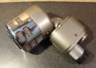
  4. Terminal size and shape. The contact with the carbon granules will affect the impedance of the mic and the efficiency.
  5. Circuit. Varying the voltage across the mic made a noticeable difference to the noise level. The transformer should be capable of taking some DC current, or a capacitor used to block the DC. (which is how I did it)

There is also a nice blog post about carbon mics at Preservation Sound.

MOTM: Siemens-Telefunken M201/1 Ribbon

We have seen an influx of weird and wonderful ribbon microphones this month, including a rash of Bang and Olufsens, half a dozen Film Industries mics, and a cardioid Toshiba BK5 copy, so we were spoilt for choice for a Microphone of the Month…. until this came along…

Telefunken M201/1 cardioid ribbon microphone

The Telefunken M201/1 was one of the very first commercial ribbon microphones. It was made by around the early 1930s and would most likely have been used for radio broadcast. These ribbon mics were a big improvement on the carbon microphones that they replaced, but in Germany they were quickly superseded by the new valve condenser microphone technology.

Telefunken logo on the M201/1 microphone

There are very few of these left in circulation – this one is in very nice condition and after a clean and a new ribbon sounds truly excellent, with a strong output not much below a modern dynamic.* After over 80 years, the magnets are still strong with a field on >5000 Gauss in the narrow 2.5 mm gap between the ribbons.

Telefunken M201/1 rear

The M201/1 is constructed around a huge horseshoe magnet, which surrounds the transformer and (presumably) some kind of acoustic labyrinth or wadding to control the pattern. This dictates the shape of the body and gives it an unusual cylindrical aspect. The ribbon sits behind a fine brass grill at the front of the mic. With the rear of the ribbon being obstructed by the magnet, the mic is almost cardioid in nature,  becoming more figure of 8 towards the very bottom of the frequency range. Two chrome B-shaped vents sit above and below the ribbon to equalise the pressure behind the ribbon. The output connection is made via a pair of screw terminals hidden behind a circular plate on the rear of the mic.

Although we can’t see the transformer, we can make some measurements. The primary and secondary DC resistances are  50 milliohms and 19 ohms respectively, and the inductances are 5.25mH and 2.43H  at 100 Hz, which gives a turns ratio of (about) 1:22. The low DC resistance and relatively high inductance point to a well designed transformer with a good quality core and thick wire for the primary. Excessive resistance in the primary winding leads to noise, so it is especially important to see a low value here.

M201 ribbon 

The ribbon itself is long and thin, and the old broken one inside the mic was fully corrugated (the one shown is a replacement). For ‘ease of service’ the ribbon is held in a frame behind the front grill. However, once in place the assembly hides the ribbon pole pieces from sight, which means that alignment is a case of trial and error, which is possibly the only weak part of the design that I have found. With the new ribbon, the mic has an output impedance of around 300 ohms.

Telefunken M201 under test

I did a test sweep of the mic in our little testing chamber.** The mic shows a strong output with good bass response, a little proximity effect below 100Hz, and a graceful roll-off above 6KHz. The noise above 14KHz are likely to be diffraction from the grill and other parts.

This microphone is thought to have been made originally by Siemens & Halske and supplied under various model numbers including the KVM3, SM3 and others, and this rather wonderful example on Martin Mitchell’s excellent microphone blog, which is just called model ‘R’. In German a ribbon mic is called a Bändchen-mikrofon. However, the name plate on this is in English, and perhaps this is the export model, with the R simply for Ribbon. There is a bit more history at Martin’s blog, which is well worth a read.

Mitchell’s Siemens type R ribbon microphone

* Testing against a Shure Beta57, the preamps were on the same gain setting for a comparable output
**Calibration is with an omni measurement mic, so there can be some bumps due to the differences in pattern picking up more or less reflections from the room.

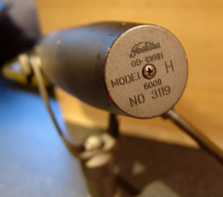
Toshiba Model H mic – RCA BK5 copy

Although now more associated with household TVs and video players, Toshiba once made some very nicely engineered studio ribbon microphones. Very often they were close copies of RCA microphones, but with a few added innovations and improvements.
Toshiba type H ribbon mic – looks like a BK5

The ‘Model H’ is no exception, being almost identical to the RCA BK5 cardioid ribbon in both looks and function. The small format ribbon sits between powerful magnets, in front of an acoustic chamber or labyrinth that takes up the middle segment of the microphone

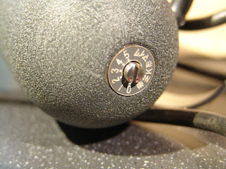
Rotating the base of the mic implements a high pass inductive filter.

In fact it seems slightly better engineered than the BK5, with a 5 position high pass filter switch that is actuated by rotating the dial at the very bottom of the microphone.

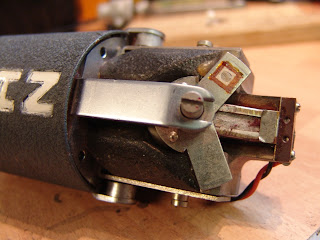
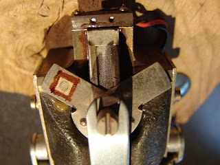
Toshiba type H ribbon

There is some additional electrical screening around the ribbon, but less acoustic baffling in front of it, which may be to give a more ‘open’ sound. In practice the ribbon is more prone to being stretched by air blasts than the RCA model.

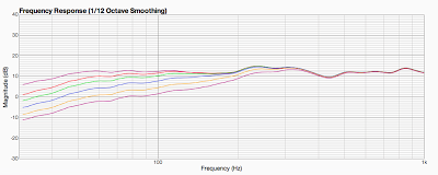
Overall the type H is a decent alternative to a ‘real’ BK5, and is a little less peaky than most of the BK5s that we have measured.

Thanks to Kore Studios.

Grampian Amplifier Speaker Set

As well as microphones, Grampian made amplifiers and other PA equipment. Here’s an old Grampian amplifier and speaker set.

I found the amp a few years ago in Dave Dee’s junk shop in York. The circuit is actually very similar to a Mullard Twenty, with the addition of a transformer balanced mic input, and several taps on the output transformer for 8 ohm loudspeaker or 100V connection. I have even used this in the past as a mic preamp for recording, for some warm and slightly dirty vocal tracks.

The speaker is a recent purchase found on GroupDIY.com. It has a rather nice and unusual tapered shape, with (no longer very) white vinyl covering. The whole set has a really cool vintage look to it – very different from today’s ubiquitous square black boxes.

I am now using this as a guitar rig – it has a great vintage valve tone with just the right amount of breakup coming from the speakers. There is plenty of volume for recording, but I would hesitate to use it for rehearsals with a modern loud drum kit!

I am unsure of the age of these but I would guess 1950s or early 60s – they don’t appear in Grampian’s 1968 product line, and presumably pre-date that. If anybody knows more, please get in touch.

Hexapup switching

Here’s an easy way to switch between the ‘split’ and ‘spread’ modes on our hexaphonic pickups, using a DPDT switch.
The E&D strings are wired in series, as are the G&e strings, observing polarity. The negative sides of these pairs are wired to the sleeve(s), and the positive ends of these are connected to a double pole, double throw switch as shown. 
The B and A strings are wired between the switch and the two outputs.  Flicking the switch then routes the E and D to either the B or the A string, and so on.
This is ideal for a tip-ring-sleeve stereo output jack. If using two mono jacks then the sleeves of these should be connected together, and to ground.

GEC Ribbon Microphone Evolution

Some time ago I posted about GEC models BCS 2370 and 2373, and how they were essentially the same design in different body shapes for different applications.

Left to right – unknown, unknown. GEC BCS2370 and 2373 mics. All have the same motor.

Since then I have come across some other ribbon microphones which may be earlier GEC models, prototypes. They are perhaps rather ugly in style, but I find their functional utilitarian style rather charming.

The two unbadged mics share some parts including a twinaxial connector at the base and rubber yoke mounts. The mic on the left is made of folded steel, whereas the one on the right is brass, with a more open grill.

All four mics are essentially the same design inside. The mic on the far left has a smaller transformer and different brand of magnet, but the pole pieces and ribbon assembly are the same. The mic in the middle of the photograph above is identical inside to the known GEC mics – with the same magnet and transformer and crumbling plastic ribbon mounts.

Remarkably, both of these mics are still working with a nice tone, although a little noisy. A good clean and service should sort that out.
The mics look very similar to the drawing in a patent by GEC and Thomas Julian, from 1947.
Drawing from a ribbon mic patent by GEC and Thomas Julian, 1947 
Which in turn is obviously inspired by the BBC-Marconi type AX ribbon mic…
Drawing from BBC-Marconi type AX ribbon mic manual.
As an aside, the GEC patent is slightly odd, in that the major innovation is that the pole pieces are held in place by the magnetic field alone, with no mechanical fasteners. That is to say the major innovation is something that they have left out, rather than something they have added to the system. The implication being that other manufacturers MUST use a screw, bolt or other fastener, or else risk infringing the patent.  It would have been interesting to see how that one would stand up in court!

Grampian GR1 & GR2 ribbon mic manuals

Grampian made some fine ribbon microphones, and the GR1 and GR2 were our Microphones of the Month in May of last year. Here’s a scan of the original Grampian GR1/2 manual.

Grampian GR1 or GR2 ribbon mic

The mic also came with a word of caution….

Don’t test a ribbon mic with a multi-meter or else…

I am particularly pleased to see the warning not to use a DC meter on these. Quite often I come across ebay auctions where the seller measures ribbon mics with a multimeter, unaware that the carrier current can bump the ribbon out of the magnetic field and stretch it. 🙁

Grampian also made matching transformers for their mics – we have a few available for sale. Here is the factory drawing for the transformer.

Grampian matching transformer wiring.

I posted some other Grampian documents last November.

Many thanks to Pete Guppy for sending this in.