We have seen an influx of weird and wonderful ribbon microphones this month, including a rash of Bang and Olufsens, half a dozen Film Industries mics, and a cardioid Toshiba BK5 copy, so we were spoilt for choice for a Microphone of the Month…. until this came along…
 |
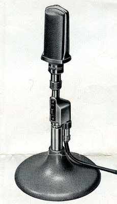
| Telefunken M201/1 cardioid ribbon microphone |
The Telefunken M201/1 was one of the very first commercial ribbon microphones. It was made by around the early 1930s and would most likely have been used for radio broadcast. These ribbon mics were a big improvement on the carbon microphones that they replaced, but in Germany they were quickly superseded by the new valve condenser microphone technology.
 |
| Telefunken logo on the M201/1 microphone |
There are very few of these left in circulation – this one is in very nice condition and after a clean and a new ribbon sounds truly excellent, with a strong output not much below a modern dynamic.* After over 80 years, the magnets are still strong with a field on >5000 Gauss in the narrow 2.5 mm gap between the ribbons.
 |
| Telefunken M201/1 rear |
The M201/1 is constructed around a huge horseshoe magnet, which surrounds the transformer and (presumably) some kind of acoustic labyrinth or wadding to control the pattern. This dictates the shape of the body and gives it an unusual cylindrical aspect. The ribbon sits behind a fine brass grill at the front of the mic. With the rear of the ribbon being obstructed by the magnet, the mic is almost cardioid in nature, becoming more figure of 8 towards the very bottom of the frequency range. Two chrome B-shaped vents sit above and below the ribbon to equalise the pressure behind the ribbon. The output connection is made via a pair of screw terminals hidden behind a circular plate on the rear of the mic.

 |
| M201 ribbon |
The ribbon itself is long and thin, and the old broken one inside the mic was fully corrugated (the one shown is a replacement). For ‘ease of service’ the ribbon is held in a frame behind the front grill. However, once in place the assembly hides the ribbon pole pieces from sight, which means that alignment is a case of trial and error, which is possibly the only weak part of the design that I have found. With the new ribbon, the mic has an output impedance of around 300 ohms.
 |
| Telefunken M201 under test |
I did a test sweep of the mic in our little testing chamber.** The mic shows a strong output with good bass response, a little proximity effect below 100Hz, and a graceful roll-off above 6KHz. The noise above 14KHz are likely to be diffraction from the grill and other parts.

This microphone is thought to have been made originally by Siemens & Halske and supplied under various model numbers including the KVM3, SM3 and others, and this rather wonderful example on Martin Mitchell’s excellent microphone blog, which is just called model ‘R’. In German a ribbon mic is called a Bändchen-mikrofon. However, the name plate on this is in English, and perhaps this is the export model, with the R simply for Ribbon. There is a bit more history at Martin’s blog, which is well worth a read.
 |
| Mitchell’s Siemens type R ribbon microphone |
* Testing against a Shure Beta57, the preamps were on the same gain setting for a comparable output
**Calibration is with an omni measurement mic, so there can be some bumps due to the differences in pattern picking up more or less reflections from the room.


